RESEARCH ARTICLE
Investigation on a Rock-breaking Drilling Mechanism by Using a High Pressure Jet Bit
Chunsheng Wang, Yang Liu*, Qiji Sun, Shan Meng, Kai Zhang, Yufei Dong
Article Information
Identifiers and Pagination:
Year: 2017Volume: 10
First Page: 12
Last Page: 18
Publisher Id: TOPEJ-10-12
DOI: 10.2174/1874834101701010012
Article History:
Received Date: 19/01/2016Revision Received Date: 07/11/2016
Acceptance Date: 10/11/2016
Electronic publication date: 23/01/2017
Collection year: 2017
open-access license: This is an open access article licensed under the terms of the Creative Commons Attribution-Non-Commercial 4.0 International Public License (CC BY-NC 4.0) (https://creativecommons.org/licenses/by-nc/4.0/legalcode), which permits unrestricted, non-commercial use, distribution and reproduction in any medium, provided the work is properly cited.
Abstract
How to effectively transfer and exert a pressure on drills in lateral drilling, and to raise the efficiency of rock-breaking and rate of penetration in a bid, is the key technology to improve the quality, speed and economic benefits of lateral drilling. Therefore, based on high pressure jet of 16-hole and 7-hole nozzles, which are suitable for lateral drilling in oilfield at the present stage, we carry out a research on the hydraulic calculation of high pressure water jet flow and the mechanism of rock-breaking. We use three-dimensional modeling software to establish models, and analyze the high pressure water jet velocity field combined with numerical simulation software. According to different injection, we calculate the local head of the two nozzles when the working fluid is pure water and the liquid-solid two phases of 4% solid content respectively, through the simulated relational expression between the local head and the injection rate to calculate the maximum speed of each hole and to ensure rock-breaking critical injection of 16-hole and 7-hole nozzles, then compare and analyze the rock-breaking effect of these two kinds of drill bits, at the same time to analyze the influence of nozzles angle on the effect of rock-breaking, so as to optimize the perfect angle of the nozzle and to provide theoretical basis for the popularization and application of lateral drilling high pressure jet rock-breaking.
1. INTRODUCTION
High-pressure water jet (HPWJ) technology is renowned for its high drilling speed, low cost, no sparks during drilling process [1-3]. Based on these advantages, it is a very good solution to the problems associated with oil production, concerning high cost and reservoir damaging [4, 5]. In the recent years, HPWJ has been widely applied to field drilling [6, 7], but with the continuous increase of lateral drilling depth, and the complexity of the well track and wellbore structure, the efficiency of rock-breaking and the speed of mechanical drilling are seriously reduced [8, 9]. However, the research about the laws of drilling efficiency influenced by the jet parameters are still inadequate [10, 11].
HPWJ is applied to the mining industry at the earliest, until in 1990s, Americans adopted the plunger type down hole booster technology to increase the pressure of 1/10 drilling fluid to about 200MPa in the well bottom, and did auxiliary bit rock-breaking experiments, which improved drilling rate by 1.5 ~ 2.5 times [12]. Meanwhile, China has made rapid progress in the technology of water jet cutting in the recent 10 years [13], and this kind of technology has made remarkable achievements on the research and application of oil jet drilling [14, 15].
In this paper, we established a three-dimensional model based on two kinds of bits which are supplied by the Daqing field. Meanwhile, with the application of numerical simulation software, according to the analysis of high water jet velocity field and mechanism of rock-breaking produced by designed nozzles are established. By the simulated relational expression between local head and the injection, combining the relationship of the compressive strength of sandstones, shear strength and the critical speed of rock-breaking, we can ensure the critical speed of rock-breaking, calculate these two kinds of bits' critical injection of rock-broking, analyze the properties of nozzle structure parameters and the nature of the working liquid influence rock-breaking, and optimize the best nozzle angle, so as to provide theoretical support for the application and provide theory support for the popularization of this technology in the field.
2. THE ESTABLISHMENT OF MODELS
When setting up the model, the structure of well bore and bits’ parameters data should be considered firstly. The structural parameters of well are provided by Daqing oilfield are summarized in Table 1. The schematic diagram of HPWJ rock breaking is shown in Fig. (1).
 |
Fig. (1). Schematic diagram of HPWJ rock breaking. |
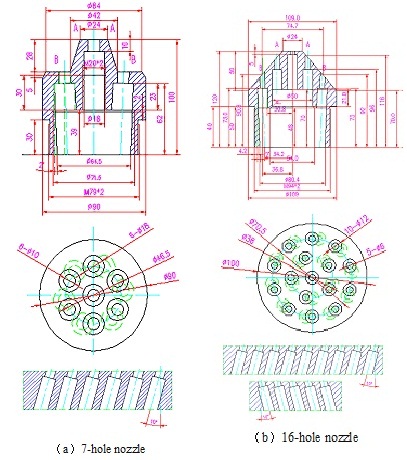
Drill bits are mainly divided into two kinds and the detailed structural parameters of the bits are showed in Fig. (2):
 |
Fig. (2). The dimension of two kinds of nozzle. |
| Well structure | Dimension | |
| Well depth | 1000m | |
| Inner casing diameter | 124mm | |
| Oil tube | outer diameter | 38mm |
| inner diameter | 32mm | |
After the 3D models were built in solidworks software, they will be segmented into several parts and all that will be divided into the grid structure type in the Gambit software. The model of dividing mesh will be simulated in FLUENT software using arbitrary Lagrange-Euler algorithm.
3. ANALYSIS CRITICAL ROCK-BREAKING SPEED OF WATER JET
To make nozzles to attain the drilling footage successfully, the destruction area of water jet is required to be greater than the largest cross-sectional area of nozzles, so that the nozzles can move forward and debris can be drained. A simple method to judge whether the hit area exceeds the maximum area of the nozzle or not is when the diffusion of water jet produced by nozzle exceeds the equivalent radius in striking areas and the speed of water jet is still over the rock-breaking critical speed. Therefore, other external factors such as the diffusion, frictional resistance and fluid resistance of water jet should also be taken into account during the actual rock-breaking. After the water jet leaving nozzles and touch rock, it is a requirement to have rock-breaking critical speed vs can make rock-breaking succeed.
Based on the theorem of momentum,
.jpg) |
(1) |
The maximum theoretical striking force at the object surface that the water jet act on can be obtained whenθ=180°,that is:
.jpg) |
(2) |
The flow formula is:
.jpg) |
(3) |
The pressure formula is:
.jpg) |
(4) |
Based on the Zhonghou Shen’s experimental conclusion, the critical pressure equation for high pressure water jet to break rock is:
.jpg) |
(5) |
Based on the shear strength and the formula (2)(3)(4)(5), the rock-breaking critical speed vs of water jet can be expressed as below:
.jpg) |
(6) |
In the formation of about 1000 meters, there are mainly medium-sandstone and mud. The compressive strength of medium-sandstone is 47.74 Mpa. Aim at medium-sandstone, we can get rock-breaking critical speed, vs respectively when the working fluid is pure water and liquid-solid two phases.
When the working fluid is pure water, the rock-breaking critical speed is shown in formula 7 below:
.jpg) |
(7) |
When the working liquid is liquid-solid two phases and the content of the solid is 4%, the density of solid-phase sand body is 1.65x10³ kg/m3, and density of the liquid-solid two phase is 1015.385 kg/m3, the critical speed of rock-breaking can be seen in formula 8 below:
.jpg) |
(8) |
4. ANALYSIS OF ROCK-BREAKING CRITICAL SPEED OF EACH HOLE IN NOZZLES
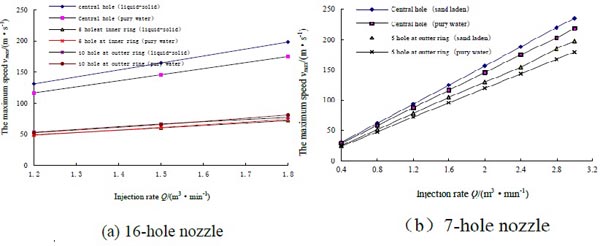
When the working liquid is water and liquid-solid two-phase, with numerical simulation software, we simulated the maximum flow velocity of each hole in 16-hole and 7-hole bits' at different injection rates and get the curve between the maximum speed and the injection rate, which is shown in Fig. (3).
At the same time, the curve simulate the critical injection corresponding with rock-breaking critical speed of each hole, the data are shown in Table 2.
| Nozzle | 7-hole nozzle | 16-hole nozzle | ||||||||
|---|---|---|---|---|---|---|---|---|---|---|
| Working liquid | Pure water | 4% liquid-solid | Pure water | 4% liquid-solid | ||||||
| Nozzle position | Center 1 | Outer 6 | Center 1 | Outer 6 | Center 1 | middle 5 | Outer 10 | Center 1 | middle 5 | Outer 10 |
| Critical Q(m3·min-1) | 0.9416 | 1.1553 | 0.8833 | 1.0598 | 0.7115 | 1.6786 | 1.5692 | 0.641 | 1.3184 | 1.4439 |
| Rock-breaking Q(m3·min-1) | 1.1553 | 1.0598 | 1.6786 | 1.4439 | ||||||
From Fig. (4), we can know that for 16-hole nozzle, the speed of central hole in liquid-solid is about 1.12 times than that in pure water. The working fluid can hardly affect the speed of 5 holes in inner ring and the 10 holes in outer ring. While for 7-hole nozzle, the speed of each hole is slightly different when the injection is low, but with the increase of injection, the speed of each hole in liquid-solid is significantly higher than that in pure water and the speed of the central hole is the largest. As shown in (Table 1), the rock-breaking critical injection of central hole in 16-hole nozzle is significantly lower than that in 7-hole nozzle. Overall, comparing the whole effect of rock-breaking, when the working fluid is liquid-solid the critical injection rate of rock-breaking is less than that in pure water. That is to say, with the same injection, the efficiency of rock-breaking in liquid-solid is better than that in pure water.
 |
Fig. (3). The relation curve of each hole's maximum speed and injection rate of these two nozzles. |
5. NOZZLE ANGLE OPTIMIZATION
Taking the 16-hole nozzle as the research object, we choose the depth of well is 1000m, the length of high pressure pipe is 50m, and the injection rate is 1.85m3/min. The following are the calculation result and analysis of high pressure jet flow field, we calculate the velocity field in direction of Y when 5 holes in the inner ring and 10 holes in the outer ring counterclockwise and clockwise tilt 5°, 8°, 10°, 12° and 15°, respectively along the tangential direction.
As shows in Fig. (4), by comparing the speed of jet section in center hole and the speed, shape of jet section at the distance of 5mm away from the center hole, when nozzles tilt at angles of 10° and 15° we find the cross section configuration of jet flow to be more regular than others. However, when the nozzle tilt at an angle of 15°, the thickness of nozzles' thread will be reduced and its strength cannot meet the requirements. When the tilt angle is 10°, the maximum speed at central nozzle is the largest, reaching 180m/s, while in the direction of cross Y at the distance of 5mm away from the outlet section of the central nozzle, the maximum speed is 110m/s, at this moment, the efficiency of rock-breaking is better than other designed nozzle angle. Therefore, we take the angle of 10°as the first choice.
 |
Fig. (4). The Y direction speed cloud graph of the central nozzle outlet cross section (left) and the position at the distance of 5mm away from the fracture surface (right). |
6. THE INFLUENCE OF BIT NOZZLE ON THE ROCK-BREAKING EFFICIENCY
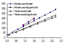
- The influence of center hole on rock-breaking compared with other nozzles, the speed of the center hole is the largest, its effect of rock-breaking is the best. Under the same injection rates, jet velocity of the center hole in 16-hole nozzle is higher than that in 7-hole nozzle. With the increase of injection rate, the velocity gap between the center hole in 16-hole nozzle and 7-hole nozzle is obviously becoming larger (as shown in Fig. (5)). From the perspective of rock-breaking, the 16-hole nozzle is more easy to break rock under the same injection rate.
 |
Fig. (5). The relation curve of central hole maximum speed and injection volume. |
-
The impact of nozzles in inner/outer rings in the direction of the circle's tangent tilt at an angle of 10° on rock-breaking.
When nozzles tilt 10° along the direction of tangent, they expand the jet areas and the tangential force produced in the tilt, preventing the nozzles to retreat in the process of drilling. Meanwhile, the tilt angle of the nozzle producing the speed stacking areas, can prevent the jet forming a single hole to stop drilling. The reason to choose the nozzle incline 10° as the best one is that the speed of the nozzle center hole is the largest at this condition, and the shape of speed diffusion areas is regular, which is more conducive to drilling. -
The influence of the angle of 2° between holes in outer ring and the axis of nozzle on the effect of 16-hole nozzle rock-breaking.
The function of the angle of 2° between holes in the outer ring and the axis of nozzles is mainly to guarantee the strength of the thread wall thickness and to increase nozzle jet area at the same time, which is helpful for drilling. In addition, due to the difference between the speed of each hole, there will be distinction between radial force of each hole, hampering the control of the well's track.
7. DISCUSSION AND CONCLUSION
We have demonstrated the use of the commercial software products Solidworks and FLUENT for creating models of complex High-pressure water jet bit and simulated fluid flows through the hole spaces. Through the simulation results, we can get the following conclusion:
- To ensure the rock-breaking critical injection rate of nozzles with 16-hole and 7-hole under different injection rate, the rock-breaking critical injection rate of the center hole in 16-hole nozzle is significantly lower than that in 7-hole nozzle. While comparing the overall effect of rock-breaking, the rock-breaking critical injection rate of 7-hole nozzle is less than that in16-hole nozzle.
- When working liquid is liquid-solid, the rock-breaking critical injection rate is less than the working fluid in pure water. That is to say, under the condition of the same injection rate, the effect of rock-breaking in liquid-solid working liquid is better than that in pure water.
- When the nozzle tilt angle is 10° or 15°, the shape of jet cross section is more regular than others, while the tilt nozzle angle is 15°, the thickness of thread in nozzle will attenuate and the strength of thread cannot meet the requirement. When he nozzle tilt angle becomes 10°, the maximum speed of the center nozzle attains the largest, up to 180m/s, which is more helpful in rock-breaking. When orifice at the outer ring of the16-hole nozzle form an angle of 2° with nozzle axis, it guarantee the strength of the thread thickness and increases the nozzle jet areas, which is conducive to drilling.
- The speed of center hole is the largest as compared with other nozzles, and its effect of rock-breaking is the best. Under the same injection rate, the nozzle with 16-hole is much easier for rock-breaking.
A significant advantage of using FULENT, or another platform, is the ability to simulate many different kinds of bit with multi-angles and fluids flowing through it. In this study, we have carried out simulations of the influence of bit nozzle on the rock-breaking efficiency. Future studies may look at different number of holes and their distribution on the efficiency of rock fragmentation.
| F | Striking force | θ | Contact angle |
| ρ | Liquid density (kg/m3) | p0 | Intensity of pressure(Mpa) |
| q | Liquid flow(m3/s) | V | Fluid velocity (m/s) |
| Q | Critical liquid flow(m3•min-1) | Vs | Critical fluid velocity (m/s) |
| A | The orifice cross area (m2) | τs | Shear strength (Mpa) |
CONFLICT OF INTEREST
The authors confirm that this article content has no conflict of interest.
ACKNOWLEDGEMENTS
Declared none.


