RESEARCH ARTICLE
Wiper Trips Effect on Wellbore Instability Using Net Rising Velocity Methods
Ali K. Darwesh*, Thorkild M. Rasmussen, Nadhir Al-Ansari
Article Information
Identifiers and Pagination:
Year: 2018Volume: 11
First Page: 14
Last Page: 28
Publisher Id: TOPEJ-11-14
DOI: 10.2174/1874834101811010014
Article History:
Received Date: 30/12/2017Revision Received Date: 11/02/2018
Acceptance Date: 14/03/2018
Electronic publication date: 30/03/2018
Collection year: 2018
open-access license: This is an open access article distributed under the terms of the Creative Commons Attribution 4.0 International Public License (CC-BY 4.0), a copy of which is available at: https://creativecommons.org/licenses/by/4.0/legalcode. This license permits unrestricted use, distribution, and reproduction in any medium, provided the original author and source are credited.
Abstract
Background:
This paper discusses the wiper trip effects on well instability in shale formations.
Objectives:
Problematic shale interval sections have been studied for the time spent on the wiper trip operations. Lifting efficiency and well wall instability change with the time analyzed. Detailed drilling operation, formation heterogeneity, rheological and filtration characteristics of polymer water-based mud are discussed. Physical and chemical properties of the drilled formation and drilling fluid are also studied.
Materials and Methods:
Wiper trips are analyzed using a typical drawing program to find the relations between the most controllable parameters. For that, two calculation models have been implemented to find the net rising cutting particles velocity in the annular. The relation between the net rising velocity and wiper trips is analyzed. Laboratory works have been done to support the findings of field work.
Results:
Strong relations have been found between the wiper trip impacts and lithology types of the penetrated shale.
Conclusion:
A modified drilling program is proposed in relation to changes in casing setting depth and drilling fluid properties that make the operations more efficient in cost and time.
1. INTRODUCTION
In general, wiper trips can be short or long for cleaning purpose or for making the wall more smooth and stable. A short trip is an action or some operation for tripping out / or in the drill string to a certain planned depth inside the open hole section. Performing a short trip helps to remove the cutting bed and to improve the smoothness of the wall. Sometimes a short trip can be done when there is a long sliding section via a mud motor. It is beneficial to do so because sliding with the mud motor creates a lot of cutting beds that are not effectively removed.
A long wiper trip is a similar action as a short trip, but the trip is longer. Typically, the drill string is pulled out from the open section and then is tripped back in the hole to the previous depth. This type of wiper trip can remove a lot of cutting beds. However, these trips take additional rig time. Not only time is spent, but also there is the risk of creating other problems as wellbore instability, formation damage, etc. Hole condition, torque, drag and field experience will dictate whether you need to do either a short trip or long wiper trip.
Drilling fluid is one of the most important elements of any drilling operation for hydrocarbon exploration [1]. Penetrating different types of formations need very close attention to the design of the drilling fluid for minimizing drilling problems and cost. Drilling fluid is the only system in the well construction that keeps us in continuous contact with the wellbore. The extent to which drilling mud properties must be controlled varies with the geologic condition [2]. A properly designed drilling fluid performs several essential functions during its circulation from the surface to the bottom of the well and up again to the surface [3]. The most important functions are to clean the well from the drilled cuttings and maintain wellbore stability. Wellbore instability may be due to chemical reactions of the drilling fluid with the drilled formations or due to mechanical issues. Many studies have been done on both the chemical and mechanical factors separately and in combination . Chenevert has studied mechanical properties of shale after hydration since the 1960s [4]. There are also many studies combining both of these factors [4-6].
Through controlling the wall stability, many operational problems toward more optimized drilling can be eliminated. In general, the primary objective of any cost control program is to maintain a low daily estimate of total expenditures for the entire drilling operation [7]. Cost of the drilling fluid ranges between10% to 20% of the total cost of a well drilling operation. For that, drilling fluid performance can affect overall well construction costs in several ways through the wellbore instability which is the largest source of well problems [3].
At the beginning of the 1950s, many soil mechanic experts were interested in the shale swelling, which are important for maintaining wellbore stability during drilling, especially in water-sensitive formations. It is reported that shale accounts 75% of all formations drilled by the oil and gas industry, and 90% of wellbore stability problems occur in shale formations [5, 6], [8, 9]. The first and most element in controlling wellbore instability is the drilling fluid passing through the (i) transport drill, cutting of the hole and separation of cuttings from the drilling fluids on the surface, (ii) formation a thin filter cake on the walls of the wellbore and preventing the inflow of drilling fluids into the formations and (iii) inhibiting the inflow of formation fluids into the wellbore [10]. Due to the swelling problems, a bridge, pack-off and tight spots will accrue. Several works focused on the selection of drilling fluid for a specific clay formation [11-13]. More recent studies on shale - fluid interactions suggest a new approach to Water-Based Muds (WBM) designs [14, 15]. Consideration is given to maintain borehole stabilization in reactive shale by reducing hydration (swelling) and/or clay dispersion. Most of the laboratory works were also done on analyzing the effect of additives on different types of drilling muds. Besides all the advances and developments in the rheological properties, still, there are some operational works like wiper trips that need more consideration and later analysis. In general, the purpose of wiper trips and reaming is to give smoother and clean well before casing running. Wiper trips and reaming can be combined with the use of the most suitable drilling mud [16]. Wiper trips can also increase the reactivity of shale formations by disturbing filter cake situation in the previously drilled intervals.
In Kurdistan, most of the well instabilities accrue in shale formations. Formations of Kolosh, Aliji and Tanjiro are the most problematic formations in drilled wells. Problems of clay dispersion or shale swelling that lead to well collapse, tight spots and pack-off are dominant problems of chemical reactions of drilling fluid with penetrated formations. Well instability for the other formations beneath theses like Shiranish, Kometan and Qamchuqa is due to mechanical instability. Wiper trips can give positive results in some formations which mostly contain limestone and negative results in other shale formations.
Daily drilling operations and most wiper trips in clay formations for more than 26 wells drilled in Taq Taq oil field, Bazian block and Meran block in Kurdistan, north of Iraq have been collected. Shale formations were the main sources of well drilling operation problems. Section 12 ¼´´ of well Bazian no. 1 (Bn-1) was selected as a key interval to be monitored closely for this study. The operation reports of drilling, mud circulating system, fluid additives, casing and cementing operations data were all collected for the 12 ¼´´ section. Following of all the wellbore problems and recording drilling parameters during wiper trips, monitoring the effect of drilling fluids additives effects on the rheological properties and its relation to wellbore stability was conducted . Data obtained from drilling and geological daily reports were analyzed to find out the effect and role of the changes in mud rheological properties. Two different calculation methods have been implemented for calculating the net rising velocity of the drilled cutting. Analyses of the cutting and coring samples were performed in Koya University laboratory for the rheological effect in the drilled section.
2. KEY WELL BN-1 LOCATION
Kurdistan region in Iraq lies within the northern part of the Zagros Folded Belt and is estimated to contain about 45 billion barrels (bbls) of Iraq’s 115 billion barrels of oil reserves, making Iraq the sixth largest oil reserve in the world [17, 18]. Tectonically, the area of this study is complex and located in the unstable platform of the Arabian plate [18]. The studied key well Bn-1 is located at the border between Low Folded Zone and High Folded Zone [19]. Bn-1 is located in the middle of three oil blocks Taq Taq, Miran and Bazian. 26 oil wells have been investigated for the effect of wiper trips operations. The Bn-1 well pad is located 1082 m above sea level on the edge of the Bazian mountain ridge [20] (Fig. 1).
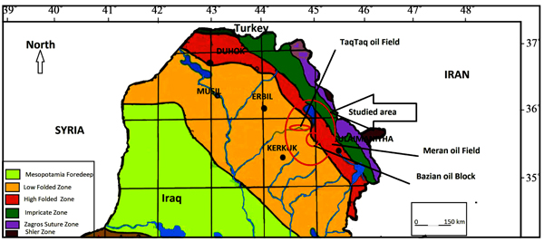 |
Fig. (1). Studied location. |
3. METHODOLOGY
3.1. Stratigraphy
Table 1 shows the top formations from the surface to the final True Vertical Depth (TVD) down to the Shiranish formation at 1800 m. The green highlighted formations in Paleocene and Cretaceous are representing the 12 ¼´´ section. These formations contain a high percentage of clay and marl. The detailed lithological description was based on collecting cutting samples after every 5 m of drilling continuously from the Mud Logging Unit (MLU). The primary reservoir targets were Shiranish, Kometan and Qamchuqa limestones of Cretaceous age. The secondary target was in the lower Jurassic and Upper Triassic.
| Age | Formation Fm. | Lithology | TOP. Fm. MD [m] |
|---|---|---|---|
| Eocene | Pila Spi | Limestone | 9.2 |
| Gercus | Marl, Conglomerate | 137,5 | |
| Paleocene | Khurmala | Limestone | 246 |
| Sinjar | Limestone | 330 | |
| Kolosh | Shale | 440 | |
| Aliji | Shale | 710 | |
| Cretaceous | Tanjero | Shale | 1673 |
| Shiranish | Limestone, Shale | 1800 |
3.2. Sub-Surface Information
The most important petroleum systems in Iraq are the Jurassic, Cretaceous, and Tertiary Petroleum Systems. Bn-1 was the first exploration oil well in Bazian block penetrated the Tertiary System to TVD of 3833m, so there was a very little information on the pore and fracture pressure gradients. Due to the shortage in prognosis information, a conservative drilling fluid program was designed based on little information gathered from offset data, especially wells drilled in west and east oil fields in Taq Taq and Miran, respectively. There were some indications that the Kolosh and Aliji formations are tectonically stressed as in the nearby Kewa Charmala no. 1 (KC-1) oil well 7 km west of Bn-1 and there was a potential that this is the case in Bn-1 also due to similarities in folding and faulting.
The Jurassic and Triassic formations may be slightly over-pressured. Limited well information was available due to the lack of oil wells penetrated to this depth in all Middle East. Heavy mud losses were expected which will affect Logging While Drilling (LWD) data transmission. The main properties of the prepared WBM-Polymer before drilling were 11 ppg, Yield Point Yp of 20-25 lb/100 ft and pH of 9.5-10.
Geologically, the low and high folded zones are characterized by harmonic folds. Cretaceous or older rocks are exposed in their cores; Paleogene and Neogene rocks form the adjacent synclines. The amplitude of the folds increases towards the NE until the anticlines override each other due to thrusting with the elimination of the intervening synclines. In the north of Iraq along the Turkish border, Paleozoic to Cretaceous rocks are exposed in the cores of tight anticlines bounded by thrust faults [18].
3.3. Reservoirs
The Tertiary oil is migrated from deeper reservoirs. The folds in high and low folds Zones grow mainly during the Pliocene. Two types of oil are contained within the Tertiary reservoirs, these are high API gravity oils in NE Iraq and low API gravity oils in the Mosul High of N Iraq. Since the Tertiary and Late Cretaceous sources in NE Iraq are immature to early mature, the light oil (37 API) in Kirkuk field must have migrated from deeper source rocks through fractures [18].
3.4. Interval Summary
The 8 ½´´pilot, Bottom Hole Assembly (BHA) was used to drill from the setting depth of 13 3/8´´ casing shoe at 1109 m down to 1843 m as a final True Vertical Depth (TVD) to penetrate Aliji, Tanjero and Shiranish formations, respectively. Losses while drilling were expected. In total thirty-meter, cores were planned to be taken periodically when instructed by the subsurface team.
Measuring and Logging While Drilling (MWD and LWD) were used to locate horizons with hydrocarbon content and to identify areas most suitable for coring. Incidences of stuck pipe and differential sticking in the offset wells were recorded in the formations of Kolosh, Aliji, and also Shiranish. All the 8 ½´´drilling BHA contain a straight mud motor to convert the drilling mode, in case the well deviates from the vertical and/or parameters shall be adjusted to correct the path. If the deviation cannot be corrected with the current BHA, it shall be replaced with a directional BHA. Black oil of around 45°API gravity with some associated gas was expected to be found in this section.
3.5. Section Operation Data
Running in Hole (RIH) 8 ½´´BHA started on November 11, 2009, after the drilled intermediate section as in Table 2, to drill down to 1436 m in the two days, with 525 gpm, 45 rpm, Weight On Bit (WOB) 2-4 tons, torque 3-4 kft.lbf, Stand Pipe Pressure (SPP) 1950 psi and 11 ppg with some minor problems on the surface, all are fixed on time (Table 2).
| Casing OD [´´] | Casing ID [´´] | Depth MD [m] | Depth TVD [m] | WT [lbs/ft] | Grade | Sections |
|---|---|---|---|---|---|---|
| 30 | 27 | 17.5 | 17.5 | 453 | X-52 | Conductor |
| 20 | 18.73 | 467 | 467 | 133 | K-55 | Surface |
| 13 3/8 | 12.415 | 1196 | 1196 | 68 | L-80 | Intermediate |
On November 13, 2009, the drilling reached the depth of 1658 m with the indications of some hole problems like tight spots, so the back reaming to 1212 m has been processed. After these tight spot indications, the decision was to start with wiper trips up and down at every drill stand once prior to each connection. At the depth 1780 m there was a deviation from the vertical drilling start to appear in azimuth 248º with 0.76º dog leg severity. To solve that, the drilling mode changed to slide drilling instead of conventional for the intervals of 1844.3 m to 1847.3 m, 1869 m to 1872 m and 1895.6 m to 1898.6 m. On November 14, 2009, the drilling reached to 1920 m, with 480 gpm, 11 ppg, 45 rpm and SPP 2300 psi. The drilling continued for the next day to its Total Depth (TD) of 2097 m, with 510 gpm, 45 rpm and SPP = 2500 psi. MWD survey was taken as required for checking the deviation & sliding to the trajectory in control till TD.
To overcome tight spots, hole pack off and other hole instability problems, the decision was to Pool Out of Hole (POOH) and lower a slick 8 ½´´BHA for more wiper trips on November 17, 2009. The mentioned BHA went down on elevators from 1196 m to 1220 m only. After experiencing tight hole, Top Drive System (TDS) was connected and started reaming down from 1220 m to 1547 m, with mud pump discharge 550 gpm, mud density 11 ppg, string rotation 80 rpm and stand pipe pressure 1400 psi. No significant losses were recorded and a moderate amount of cuttings observed coming back over shakers.
From November 18, 2009, up to the end of December 2009, there was no significant production in drilling. All the operations were going around solving the instability of the well that leads to the stuck of logging tools and then to making a side track as summarized in Table 3.
| Date | Operation | Results |
|---|---|---|
| Nov 13, 2009 | Drilling to the depth of 1870 m | Well instability problems and deviation start to walk |
| Nov 14, 2009 | Drilling to the depth of 1920 m | Well instability problems |
| Nov 15 to 17, 2009 | Wiper trip and reaming and change BHA | Well instability problems |
| Nov18, 19 and 20 2009 | Increase mud weight to 12 ppg mud and wiper trips, Loss Circulating Materials (LCM) commenced. |
Problems in well stability not solved |
| Nov 20, 2009 | Rig up Super Combo and start Run # 1 for logging | Logging performed from 1473 m upward only due to that bridge |
| Nov 20 to Nov 30 2016 | Run # 2,3 and 4 Wiper trips and reaming |
Problems in well stability not solved and in increase |
| Nov 30; 2009 | Fishing of wire line logging tools | failed |
| Dec 1, 2009 | Opening the well to 12 ¼´´ to 1750 m top of the fish | |
| Dec 2,3 and 4 2009 | Fishing operating, wiper trips and reaming | Fishing failed Hole problems not solved |
| Dec 5 | Start side tracking and drilling to 1929 m with 12 ¼´´ BHA | |
| Dec 5 to Dec 10 | Ream and wiper trips | Hole problems not solved |
| Dec 11, 2009 | First, run of casing 9 5/8´´ | Failed at 1318 m due to the bridge. |
| Dec 12 to Dec 31 | To attempts of casing running, many wiper trips and reaming | Casing failed. Well instability problems not solved |
3.6. Wiper Trip Records
After the first unsuccessful casing-running and POOH all casing back to the surface, the first long wiper trip commenced as shown in Fig. (2). The most problematic interval 1600 m to 2000 m, was mostly composed of clay and marl from the formations of Tanjero and Shiranish.
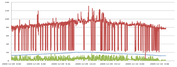 |
Fig. (2). Wiper trip from1600 m to 2000 m up and down on December 9 and 10, 2009 in hours. |
Here, a symmetric profile between tripping down and tripping up in terms of parameters Weight on Hook (WOH) and Torque can be observed. Both parameters are in the same value range during wiper trip down and up. The wide ranges of these two parameters are indicators of hard reaming and well instability. The main reason could be the formations that are tectonically stressed like KC-1 well which is about 7 km west of Bn-1. Continues cutting on the shakers and high values of WOH and Torque are strong indicators which indicate that there is a continuous collapse due to unbalanced pressure or the interval is under stress [1] (Fig. 3). Forces acting in the formation, push the wall of the hole inward which leads to collapse if not stabilized with mud [16].
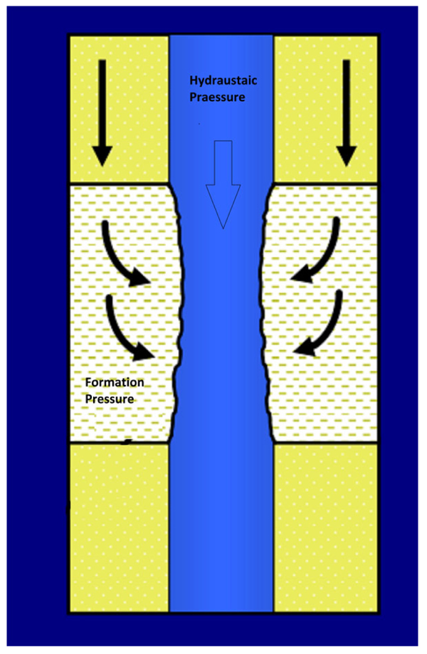 |
Fig. (3). Under stress formation due to unbalanced hydrostatic pressures. |
Figs. (4-8) show more records of long wiper trips after some improvements in the drilling fluid properties like density and viscosity. In comparing Fig. (4) with the first part of Fig. (7), the improvements in torque and WHO can be observed easily, as was mentioned in pervious researches [5], [21].
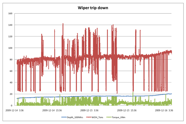 |
Fig. (4). Wiper trip down from 1700 m to 2000 m, December 16, 2009, in hours. |
Figs. (5A, 6, 7 and 8) represent more long wiper trips after each change in fluid properties. Figs. (4 and 5) represent a complete wiper trip up and down at two different times to show the time effect. In Fig. (5), after seven days and many improvements on mud properties, the situation which is about the same in terms of the value of the high range of WHO and the torque can be observed. Hole instability increased with the time, despite some improvements in the drilling fluid properties which is the main reasons to the long-time gap between the first penetrating time to the casing time [22].
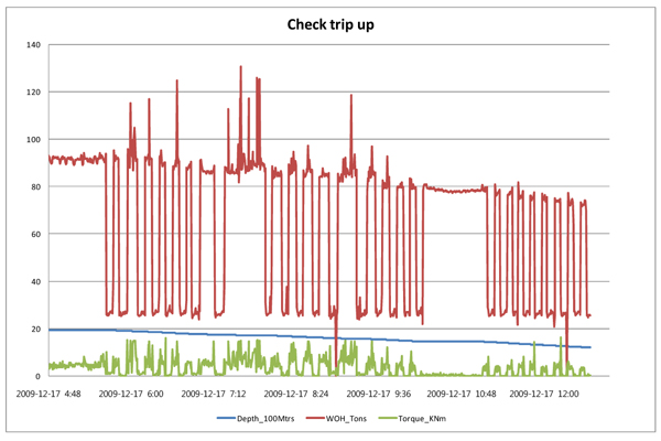 |
Fig. (5A). Wiper trip up from 2000 m to 1700 m, December 17, 2009, in hours. |
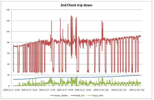 |
Fig. (5B). Wiper trip down from 1700 m to 2000 m, December 17, 2009, in hours. |
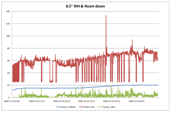 |
Fig. (6). Wiper trip from 1760 m down to 2000 m, December 22 and 23, 2009 in hours. |
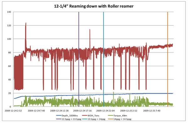 |
Fig. (7). Wiper trip from 1700 m down to 2000 m, December 24 and 25, 2009 in hours. Vertical violet, blue and orange lines show time of increase mud density. |
Time-effectiveness is clearer in the wiper trips records in Figs. (6, 7 and 8), where both parameters WOH and Torque remained at about the same values with significant improvement with an increase of the fluid density from 11 ppg to 14.5 ppg. Replacing the reaming 8 ½´´ BHA with 12 ¼´´, BHA had been decided prior to run the casing as soon as possible.
The increase in the mud density gradually from 11 ppg to 14.5 ppg gave a relatively good result in controlling well instability in the lower part. Increasing the density caused the hydrostatic pressure to be increased also and overcome the dominant problems like bridge and packing-off to some extent. This supported the expectation that the lower part problems are different from the upper part problems in this section in term of well instability. Mechanical instability begins with penetrating Shiranish or from somewhere in the transition interval between Tanjero and Shiranish formations.
On December 31, 2009, reaming and washing were performed using 14.5 ppg drilling mud without significant resistance to 1945 m [23]. January 1, 2010, the third attempt of casing operation commenced successfully. Using waterbush in the last attempt of RIH casing made the casing pipes to rotate by TDS (Top Drive System) and pass the bridged intervals to a depth till 1843 m. Casing operation was bridged at 1843 m with no ability to lower more or POOH. Parameters used in running the casing were, WOH from 16 to 40-ton, rotation 10 rpm, mud flow 40 spm and 14.5 ppg WBM-Polymer. This depth became the setting depth of 9 5/8´´ casing.
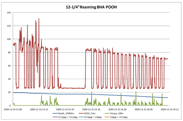 |
Fig. (8). Wiper trip from 2000 m up to 1760 m, December 25, 2009, in hours. |
4. NET RISING CALCULATIONS
Net rising calculations are used here to verify and check the validation of the wiper trips operations before the casing-running. For that, if the cutting increased with the wiper trip operations, this will be a strong indicator for other problems that cannot be solved with the wiper trips [24]. In this case, rapid improvement of parameters like flow rate, annular velocity, pipe rotation, ROP, mud weight (density), mud rheology and cutting size/shape should be performed. These parameters directly affect the standpipe pressure and frictional pressure down the hole [25]. The first and most effective parameter in this relation is the mud density. Through the mud density, there will be a high possibility to return pressure balance between the formation pressure and hydrostatic pressure and thereby, prevent settling more cutting down the hole. To find out the effect of wiper trips in Bn-1 on improving the drilling operations, we will start with the calculation of cutting slip velocity [26].
In general, there are two methods to calculate cutting slip velocity [27]. If the net rising velocity is positive, it means that the drilling fluid properties and the flow rate are with accepted values to carry out cutting to the surface. In this case, the wiper trips will leave a positive effect on the operations. On the other hand, if net rise velocity is negative, it means that the flow rate and fluid properties are NOT accepted to carry out the cuttings [28]. In this case, all the effects with wiper trips operations without any other improvement are useless.
The first method depends mostly on the real field data using equations (1 - 3) below:
The annular velocity Av is provided by equation (1):
 |
(1) |
Where, Av is an annular velocity in ft/min. Q is the flow rate or Triplex Pump Output in gpm (gallon per minute), Dh is the diameter of the hole in inch and Dp is the diameter of drill pipe in inch.
The cutting slip velocity Vs is given in equation (2):
 |
(2) |
Where Vs is the cutting slip velocity in ft/min, Pv is the plastic viscosity in centipoise, Mw is mud weight in ppg., Ds is the diameter of cutting in inch and Mws is cutting density in ppg.
The net rise velocity Nv is given by equation (3):
 |
(3) |
The general formula for getting Q in units of gpm is given in equation (4):
 |
(4) |
Where, SPM is Stroke per minute, R is the liner size (inch) and Ls is the stroke length (inch).
Calculation of the pump output Q in gpm before and after modification of mud properties gives 441.9 gpm and 368.2 gpm, respectively by using equation (4), where a Ls=6.5 inch and SPM=90 before and SPM=75 after modification. Input data for the equations above are given in Table 4.
| Wiper Trips when the drilling fluid properties not improved on 9.12.2009 | ||||||
|---|---|---|---|---|---|---|
| Q (gpm) | Dh (in) | Dp (OD) inch | Pv (cps) | Mw (ppg) | Mws (ppg) | Ds (in) |
| 441 | 12 ¼`` | 5 | 25 | 12 | 20 | 0.2 |
| Wiper Trips when the drilling fluid properties not improved on 9.12.2009 | ||||||
| 368 | 12 ¼`` | 5 | 34 | 14.5 | 35 | 0.1 |
The net rising velocity is estimated to Nv = 55 ft/min and 38.67 ft/min before and after mud modification, respectively. The increase in hydrostatic pressure by changing the mud properties prevents wall collapse and increases wall stability at the same time as a positive velocity is maintained. Thus, wiper trip was not necessary.
The second method for calculating the net rising velocity is quite different from the first method [27]. However, it is still a straight forward calculation. The cutting slip viscosity in centipoise is given by equation (5):
 |
(5) |
Where n is the power law exponent given by equation (6)
 |
(6) |
Where, θ600 is a value at 600 viscometer dial reading and is a value at 300 viscometer dial reading.
The fluid consistency K is given by equation (7)
 |
(7) |
The annular velocity Av is calculated by equation no. (1) and the slip velocity (Vs) in ft/min from equation (8):
 |
(8) |
The net rise velocity is again calculated from equation (3) above. Input data for the equations above are given in Table 5.
| Wiper Trips when the drilling fluid properties not improved on 9.12.2009 | |||||||
|---|---|---|---|---|---|---|---|
| θ300 | θ600 | Q (gpm) |
Hole Diameter (in) | Drillpipe (OD) inch | MW (ppg) | Ds (in) |
Mws ppg |
| 54 | 79 | 441 | 12 ¼`` | 5 | 12 | 0.2 | 20 |
| Wiper Trips when the drilling fluid properties not improved on 9.12.2009 | |||||||
| 68 | 102 | 368 | 12 ¼`` | 5 | 14.5 | 0.1 | 35 |
The net rising velocity is estimated to Nv = 76.3 ft/min and 63.7 ft/min before and after mud modification, respectively. The estimated flow rate is good for hole cleaning because the annular velocity is more than cutting slip velocity.
5. RESULTS
Koya University laboratories were used in preparing many WBM-polymer drilling fluids with different densities, pH and other rheological parameters. High Pressure - High Temperature (HPHT) filtration tests were performed and a Viscosity-Gel meter (VG) was used to find rheological properties based on the Bingham-Plastic model equations.
- The drilled 12 1/4'' section can be divided into two parts. The upper part is composed of Kolosh and Aliji formations that contain a high percentage of clay and the lower part is mostly limestone of the Shiranish formation with a low percentage of clay and this was indicated by previous researchers like Saad Z. Jassim and Jeremy C. Goff also [29].
- Hole problems in the upper part are mainly caused by chemical interactions between drilling fluid and a high percentage of clay like problems of tight spots and bridges. The problems in the lower part are mostly mechanical instabilities due to the high percentage of limestone which can be solved through the increase of mud density. Problems like well pack-off and bridge were more dominant in this part [23].
- Casing setting point of surface section locates inside the Aliji formation making the formation of two parts and a weak setting point as been shown in Fig. (11).
- Mud logging records unit and cutting sampling matched the lithological description. The lithological description of the penetrated formations Aliji, Tanjero and Shiranish is presented in Table (6). The Aliji formation contains a higher percentage of clay than Tanjero and Shiranish. The last two formations are composed mainly of fractured marly limestone with some clay beds.
| Interval Formation [m] | Lithology | Drilling Parameters | |||||
|---|---|---|---|---|---|---|---|
| Marl [%] | Siltstone [%] | Limestones [%] | WOB [ton] | MW [ppg] | SPP [psi] | Pump Discharge [gpm] | |
| 1200 – 1255 Aliji - Tanjero | 80 - 90 | 10 - 15 | 5 -10 | 2-12 | 11.0 | 2075 | 520 |
| 1255 – 1320 Tanjero | 30 - 40 | 10 - 15 | 30 - 40 | 3-6 | 11.0 | 1950 | 520 |
| 1320 – 1660 Tanjero | 40 - 50 | 15 - 20 | 10 - 20 | 1-6 | 11.00 | 1950 | 480 |
| 1660 – 1855 Tanjero - Shiranish | 15 - 20 | 10 - 15 | 70 - 90 | 3 - 18 | 12.00 | 3036 | 768 |
| 1855 – 1995 Shiranish | 20 - 25 | 5 -10 | 60 - 75 | 2 - 10 | 12.00 | 2970 | 742 |
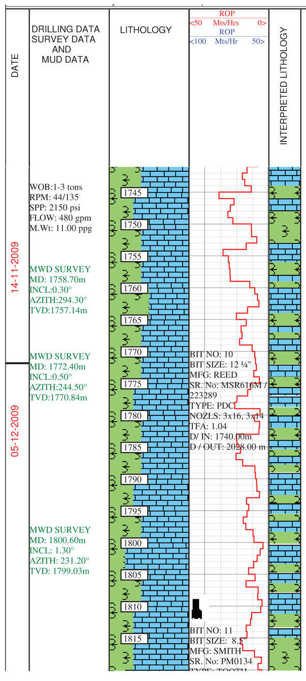 |
Fig. (9). Part of MLU data of Bn-1 oil well [30]. |
- All the field and laboratory tests enabled us to realize that the density between 11-12 ppg can give a very good over-balanced drilling operation in drilling the upper part of 12 ¼´´ section and 14-15 ppg for the lower part.
- Polymers like PAC and PHPA optimize mud rheological properties. Table 7 and Fig. (10) show the laboratory results of Equivalent Mud Density (EMD) for each of the penetrated formations in the 12 ¼´´ section.
| Formation | Depth [m] TVD | Pore Pressure [ppg] | Temperature [°C] |
|---|---|---|---|
| Kolosh | 440 – 710 | 11 | 45 – 51 |
| Aaliji | 710 – 1673 | 12 | 51 – 72 |
| Upper Shiranish | 1673 – 1943 | 14.4 | 72 – 78 |
| Lower Shiranish | 1943 – 2279 | 14 | 78- 86 |
- Drilling performance reduced due to long time and high cost consumed for the wiper trips operations towards solving the well instability [30].
- Instability of shale formation caused the stuck of BHA, downhole tools fishing, loss of equipment and side tracking operations.
- High chemical reactivity of the shale resulted in poor hole logging, inability to the land casing on the planned setting point and poor cementing conditions/jobs. Essentially increase in nonproductive time and increase in total drilling cost.
 |
Fig. (10). Bn- Lab calculated pressure and equivalent mud weight EMW with depth. |
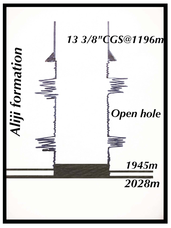 |
Fig. (11). Drilled sections in Bn-1 Side Track 1 |
CONCLUSION
- Little over balanced mud property can sustain well stability in the upper part of 12 ¼´´ section where the chemical reactions are the main causes of drilling hole problems.
- Based on the positive results of the calculated net rising velocity, the lower part of the section is tectonically stressed and composed mainly of limestone. Wiper trips in tectonically stressed sections will be the waste of time if we do not return the over balance situation.
- Wiper trips in the upper part of 8 ½´´ section will leave a positive effect and negative effect on the lower part of the section.
- PHPA (partially hydrolyzed polyacrylamide) improves rheological properties like viscosity and gel strength and makes a thin gelatin barrier covering borehole wall. These improvements decrease the invasion of the formation and clay dispersion also.
- Changing the drilling program for the surface section in Fig. (11) to drill and case all Aliji formation with the surface section will help to overcome many challenges and difficulty in the intermediate section.
- Wiper trips with homogenous improve in drilling fluid properties can give positive effects in solving problems in the 12 ¼´´section.
CONSENT FOR PUBLICATION
Not applicable.
CONFLICT OF INTEREST
The authors declare no conflict of interest, financial or otherwise.
ACKNOWLEDGMENTS
The authors would like to thank the support from the Ministry of Higher Education in Kurdistan (via Koya University Laboratory). Thanks also to our colleagues from the Luleå University of Technology in Sweden, Korea National Oil Corporation (KNOC) for many valuable discussions and technical support.
REFERENCES
| [1] | Rabia H. Well Engineering & Construction 2002. |
| [2] | Gatlin C. Drilling and Well Compitions 1960. |
| [3] | Khodja M, Canselier JP, Bergaya F, et al. Shale problems and water-based drilling fluid optimisation in the hassi messaoud algerian oil field. Appl Clay Sci 2010; 49(4): 383-93. |
| [4] | Chenevert M. Shale control with balanced-activity oil-continuous muds J Pet Technol 1970; 22(10): 1-309-16. |
| [5] | Chen G, Chenevert ME, Sharma MM, Yu M. A study of wellbore stability in shales including poroelastic, chemical, and thermal effects. J Petrol Sci Eng 2003; 38(3): 167-76. |
| [6] | Hale A, Mody F. Borehole-stability model to couple the mechanics and chemistry of drilling-fluid/shale interactions. J Pet Technol 1993; 45(11): 1093-101. |
| [7] | Preston L. DRILLING PACTICES MANUAL 2nd ed.. 1985. |
| [8] | Coelho LC, Soares AC, Ebecken NFF, Alves JLD, Landau L. The impact of constitutive modeling of porous rocks on 2-D wellbore stability analysis. J Petrol Sci Eng 2005; 46(1): 81-100. |
| [9] | Darley H. A laboratory investigation of borehole stability. J Pet Technol 1969; 21(07): 883-92. |
| [10] | Dingsøyr E, Pedersen E, Taugbøl K. Oil based drilling fluids with tailor-made rheological properties: Results from a multivariate analysis 2004; 12 |
| [11] | Darley H. A laboratory investigation of borehole stability. J Pet Technol 1969; 21(07): 883-92. |
| [12] | Lal M. Shale stability: Drilling fluid interaction and shale strength 1999. In: SPE Asia Pacific Oil and Gas Conference and Exhibition; 1999. |
| [13] | Pernot VF. Troublesome shale control using inhibitive water-base muds 1999. |
| [14] | Lomba RF, Chenevert M, Sharma MM. The role of osmotic effects in fluid flow through shales. J Petrol Sci Eng 2000; 25(1): 25-35. |
| [15] | Van Oort E. On the physical and chemical stability of shales. J Petrol Sci Eng 2003; 38(3): 213-35. |
| [16] | Bommer PM. A Primer of Oilwell Drilling 2008. |
| [17] | Abdula R. Petroleum source rock analysis of the Jurassic Sargelu Formation, northern Iraq 2010. |
| [18] | Jassim SZ, Goff JC. Geology of Iraq, DOLIN, sro, distributed by Geological Society of London 2006. |
| [19] | Fouad S. Tectonic map of iraq, scale 1: 1000 000 3rd Ed.. 2012. |
| [20] | Kurdistan M. Ministry Of Natural resources [Online]. available: http://mnr.krg.org/index.php/ku/structural-domain |
| [21] | Chenevert ME. Shale alteration by water adsorption J Petrol Tech 1970; 22(9): 1-141. |
| [22] | Darwesh A. RIH intermediate section casing in bazian-1 exploration oil well. WIT Trans Eco Environ 2014; 186: 559-69. |
| [23] | Korean National Oil Corporation. Daily Drilling reports 2009. KNOC, Kurdistan, Iraq, Rep. 3 |
| [24] | Li J, Walker S. Sensitivity analysis of hole cleaning parameters in directional wells. SPE J 2001; 6(04): 356-63. |
| [25] | Vajargah AK, van Oort E. Determination of drilling fluid rheology under downhole conditions by using real-time distributed pressure data. J Nat Gas Sci Eng 2015; 24: 400-11. |
| [26] | Bourgoyne AT Jr, Millheim KK, Chenevert ME, Young F Jr. Applied drilling engineering chapter 8 solutions. Society of Petroleum Engineers 1986. |
| [27] | Lapeyrouse NJ. Formulas and calculations for drilling, production, and workover, Gulf professional publishing 2002. |
| [28] | Aadnoy BS. Fundamentals of drilling engineering 2011. |
| [29] | Jassim SZ, Goff JC. Geology of Iraq, DOLIN, sro, distributed by Geological Society of London 2006. |
| [30] | Korea National Oil Corporation. MLU DATA, KNOC 2009. Kurdistan, iraq, Rep. MLOG 0-627 |


