RESEARCH ARTICLE
Analysis of Spatial Distribution Pattern of Reservoir Petrophysical Properties for Horizontal Well Performance Evaluation-A Case Study of Reservoir X
Aidoo Borsah Abraham1, *, Annan Boah Evans1, Brantson Eric Thompson2
Article Information
Identifiers and Pagination:
Year: 2019Volume: 12
First Page: 1
Last Page: 13
Publisher Id: TOPEJ-12-1
DOI: 10.2174/1874834101912010001
Article History:
Received Date: 05/11/2018Revision Received Date: 14/02/2019
Acceptance Date: 20/02/2019
Electronic publication date: 23/04/2019
Collection year: 2019
open-access license: This is an open access article distributed under the terms of the Creative Commons Attribution 4.0 International Public License (CC-BY 4.0), a copy of which is available at: https://creativecommons.org/licenses/by/4.0/legalcode. This license permits unrestricted use, distribution, and reproduction in any medium, provided the original author and source are credited.
Abstract
Introduction:
Building a large number of static models to analyze reservoir performance is vital in reservoir development planning. For the purpose of maximizing oil recovery, reservoir behavior must be modelled properly to predict its performance. This requires the study of the variation of the reservoir petrophysical properties as a function of spatial location.
Methods:
In recent times, the method used to analyze reservoir behavior is the use of reservoir simulation. Hence, this study seeks to analyze the spatial distribution pattern of reservoir petrophysical properties such as porosity, permeability, thickness, saturation and ascertain its effect on cumulative oil production. Geostatistical techniques were used to distribute the petrophysical properties in building a 2D static model of the reservoir and construction of dynamic model to analyze reservoir performance. Vertical to horizontal permeability anisotropy ratio affects horizontal wells drilled in the 2D static reservoir. The performance of the horizontal wells appeared to be increasing steadily as kv/kh increases. At kv/kh value of 0.55, a higher cumulative oil production was observed compared to a kv/kh ratio of 0.4, 0.2, and 0.1. In addition, horizontal well length significantly affects cumulative oil production of the petroleum reservoir studied.
Results:
At kv/kh of 0.55, the results of the analysis showed a rapid decrement in cumulative oil production as the horizontal well length decreases. Considering horizontal well length of 3000 ft, 2000 ft, and 1500 ft, a minimum cumulative oil production was obtained from a horizontal well length of 1500 ft.
Conclusion:
The geostatistical and reservoir simulation methods employed in this study will serve as an insight in analyzing horizontal well performance.
1. INTRODUCTION
Reservoir development planning and well performance evaluation is essential for oil and gas exploration and development (E&P) project. In the past years, horizontal wells have been widely used in the exploration and development of unconventional and low permeability reservoirs [1-7]. Generally, E&P investment decision is based on several factors including reservoir performance predictions. To achieve sound reservoir performance predictions, a reliable static model is needed. Geostatistics seeks to improve prediction by developing different types of static models. It uses techniques that do not average important reservoir properties to produce more realistic geological model of reservoir heterogeneity. Like the traditional deterministic method, “hard” data is indisputably preserved where they are known and interpretative “soft” data where they are informative [8]. In addition, petrophysical properties distribution is essential for building static models of the reservoir. These properties involved may include the porosity, permeability, thickness, saturation, rock facies and rock characteristics, faults and fractures [9]. For many years now, geostatistical techniques have been an acceptable technology used for reservoirs’ characterization [10-13]. The main purpose for using geostatistics is to analyze and provide adequate assessment of geological uncertainty and a realistic model of reservoir property variability. Geostatistics attempts to generate many realizations of a two dimensional variable that represents the reservoir quality within the stratigraphic interval [14].
More importantly, the decision on how to increase oil recovery and maximize the profitability of field development projects is the focal point. Therefore, an extensive evaluation of certain decision variables such as production scheduling parameters, reservoir properties, well types, location to drill new wells and effective technique to obtain the best economic strategies are required. Also, consideration should be given to the spatial distribution of geological and rock properties such as porosity and permeability in order to locate potential hydrocarbon zones for drilling activities. This involves extensive analysis and critical evaluation of development strategies to produce the greatest amount of hydrocarbons within the expected economic limits. Several techniques have been adopted to achieve efficient reservoir development process which significantly affects the productivity and economic benefits of an oil reservoir. However, the purpose of this study is to analyze the spatial distribution pattern of reservoir petrophysical properties to evaluate horizontal well performance. In this study, spatial based modeling approaches and reservoir simulation were used as key evaluating factor for the development of the reservoir to improve its productivity.
2. RESERVOIR DESCRIPTION
The reservoir studied in this research synthetically named reservoir X is located in Plum Bush Greek Field, Washington County, Colorado. It has a geometry comparable to channel sand with a gently west dipping slope. The structure has a maximum elevation difference of approximately 60 ft with a thickness of approximately 40 ft to 50 ft. The average net-pay thickness is 20 ft. The compressibility of the formation is approximately 3.0 x 10⁻⁶ psi-1. At 9290ft reference depth, the initial oil and gas saturation are estimated to be Soi=77%, and Swi=23% respectively. At the reference depth of 9290 ft, initial formation pressure is measured to be 4800 psia. Reservoir X consists of poorly-to-well-sorted Cretaceous Dakota J sands. The reservoir sands depict excellent reservoir quality with permeability ranging from 250 mD to 300 mD. The average effective porosity of the reservoir is 22% [15].
3. MATERIALS AND METHODS
3.1. Materials Used
The data used for this research include: isoporosity map, isopermeability map, structure, and isopach maps of reservoir X. The maps were digitized and their corresponding coordinates were used to produce Digital Terrain Model (DTM) and contour map of top of sand structure of reservoir X as shown in Figs. (1 & 2). The permeability, porosity and thickness values obtained from the isopermeability, isoporosity, and isopach maps were used for the Geostatistical modeling.
3.2. Reservoir Characterization and Static Modeling
The reservoir has an aerial extent of about 620 acres with the net thickness of about 40ft. The average effective porosity of the reservoir is 22%, with permeability ranging from 250mD to 300 mD.The maximum and minimum values of the X and Y coordinates of the properties location were used to estimate the region of stationarity as shown in Table 1.
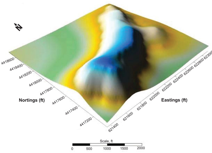 |
Fig. (1). Digital terrain model of Reservoir X. |
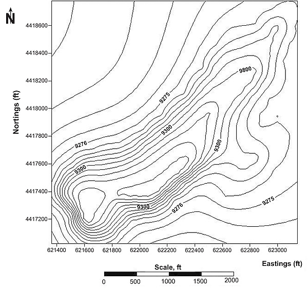 |
Fig. (2). Contour map of top of sand structure of reservoir X. |
Stanford Geostatistical Modeling Software (SGEMS), an open-source computer package for solving problems involving spatially related variables, was employed. Each reservoir property data set was estimated using variogram models, Ordinary Kriging (OK), Sequential Gaussian Simulation (SGS), and Sequential Indicator Simulation (SIS). Generally, anisotropic variograms were considered to adequately capture the spatial variation between the data points. The properties evaluated are permeability, porosity, and net thickness. These properties were evaluated in each of the eight layers within the reservoir. OK was used to estimate permeability, porosity, and thickness values at the unsampled location. SGS was carried out on porosity and thickness, while SIS was carried out on the permeability model with many realizations produced in each layer. Philips [14] proposed that one realization is only one possible outcome, many realizations normally need to be simulated to assess variability and probability of occurrence.
3.3. Porosity Distribution Model
In this study, porosity was modeled using SGS. Fig. (3) shows porosity distribution map generated with OK and SGS. The spatial variation in the porosity data points was well captured in one variogram direction. Variogram analysis was conducted on the porosity data set to subsequently aid in the generation of equiprobable realizations. Exponential model was used to fit the data set by visual inspection. The modeling input parameters are shown in Table 2.
3.4. Permeability Distribution Model
Modeling of permeability was carried out using SIS. Fig. (4) shows permeability distribution map generated with OK and SIS. The modeling input parameters are shown in Table 3. The OK map shows good lateral continuity of high permeability values along the south west and north east corner of the grid block. Gaussian variogram model was used to fit the permeability data set from the variogram analysis conducted. Omni-directional variograms were used to appropriately capture the spatial correlation in the permeability data set.
| Cell Dimensions (in feet) Value |
|---|
| Number of cells in the X-direction 96 |
| Number of cells in the Y-direction 96 |
| Number of cells in the Z-direction 20 |
| Minimum value of X-coordinates, Xmin 621359.55 |
| Maximum value of X-coordinates, Xmax 623285.70 |
| Minimum value of Y-coordinates, Ymin 4416890.17 |
| Maximum value of Y-coordinates, Ymax 4418816.32 |
| Parameters | Value |
|---|---|
| Number of Lags | 60 |
| Lag Separation (ft) | 45 |
| Lag Tolerance (ft) | 75 |
| Number of Directions | 1 |
| Azimuth (degree) | 0 |
| Dip (degree) | 0 |
| Tolerance (degrees) | 90 |
| Bandwidth(ft) | 1200 |
| Nugget Effect (γ) | 0.35 |
| Number of Structures | 1 |
| Sill (γ) | 0.53 |
| Minimum Range (ft) | 89 |
| Medium Range (ft) | 221 |
| Maximum Range (ft) | 512 |
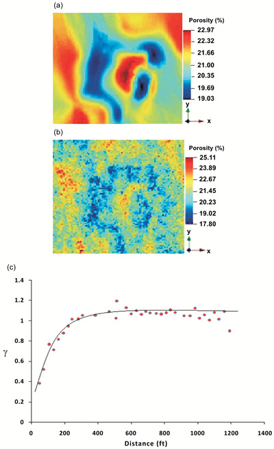 |
Fig. (3). Spatial distribution of porosity;(a) ordinary kriging (b) a plot of SGS (c) variogram model. |
3.5. Thickness Distribution Model
Modeling of net thickness was carried out using SGS. Fig. (5) shows thickness distribution map generated from OK and SGS. The model shows lateral continuity from the southeast to the northwest corner of the grid block.
This represents the principal direction of the variogram. Gaussian variogram model was used to fit the thickness data set from the variogram analysis conducted. Omni-directional variograms were used to adequately capture the spatial correlation in the thickness data set. Table 4 shows the modeling input parameters.
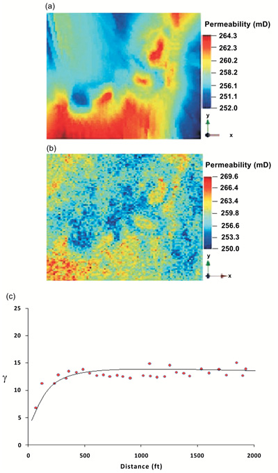 |
Fig. (4). Spatial distribution of permeability; (a) ordinary kriging (b) a plot of SIS (c) variogram model. |
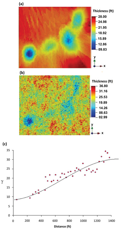 |
Fig. (5). Spatial distribution of net thickness; (a) ordinary kriging (b) a plot of SGS (c) variogram model. |
4. DYNAMIC RESERVOIR MODELLING
Sensor 6K compositional and black-oil reservoir simulator was used for the reservoir simulation phase of this research [16]. Several SPE comparative solution examples were used to test the accuracy and efficiency of the model code formulation and results. Three black oil problem, SPE1, Comparison of Solutions to a Three Dimensional Black Oil Reservoir Simulation Problem [17], SPE2, A Three-Phase Coning Study [18] and SPE9, An Expanded Three-Dimensional Problem with a Geostatistical Distribution of Permeability [19], were run as well as two compositional cases, SPE3, Gas Cycling of Retrograde Condensate Reservoir [20], and SPE5, Evaluation of Miscible Flood Simulators [21]. All the runs gave identical results and good agreement was obtained on validity of the compositional and black-oil reservoir simulator [16].
 |
Fig. (6). Well location in reservoir X. |
| Parameters | Value |
|---|---|
| Number of Lags | 50 |
| Lag Separation (ft) | 60 |
| Lag Tolerance (ft) | 105 |
| Number of Directions | 1 |
| Azimuth (degree) | 0 |
| Dip (degree) | 0 |
| Tolerance (degrees) | 90 |
| Bandwidth (ft) | 6900 |
| Nugget Effect (γ) | 3 |
| Number of Structures | 1 |
| Sill (γ) | 10 |
| Minimum Range (ft) | 112 |
| Medium Range (ft) | 310 |
| Maximum Range (ft) | 588 |
The phases present in reservoir X are water and oil. The model represents a 620 acre field (approximately 6000ft x 5400ft) with three production wells located in grid block 7:7:4, 2:3:6 and 9:4:5 respectively. In this study, 10 years’ production period was considered. Perforations were shut down as soon as water cut reaches 80%. Fig. (6) and Table 5 shows wells location in reservoir X and the initial fluids in place after the initialization run.
The porosity, permeability, and thickness generated were used to populate the reservoir model. The simulation grid and various rock properties in each grid cell were specified in the grid section. From these properties, the pore volumes of the grid blocks and the inter-block transmissibilities were estimated by the simulator. The average effective porosity is 22% and permeability ranges from 250mD to 300 mD. Fig. (7) shows the relative permeability curve used while a summary of the reservoir properties are shown in Table 6.
| Parameters | Value |
|---|---|
| Number of Lags | 40 |
| Lag Separation (ft) | 30 |
| Lag Tolerance (ft) | 80 |
| Number of Directions | 1 |
| Azimuth (degree) | 0 |
| Dip (degree) | 0 |
| Tolerance(degrees) | 90 |
| Bandwidth (ft) | 6900 |
| Nugget Effect (γ) | 7.9 |
| Number of Structures | 1 |
| Sill (γ) | 23 |
| Minimum Range (ft) | 150 |
| Medium Range (ft) | 720 |
| Maximum Range (ft) | 1320 |
4.1. Spatial Distribution Model of Pressure and Saturation
The reservoir is strongly supported by an aquifer and the invading water helps to move the oil to the producing wells. The pressure within the reservoir is uniformly distributed and it ranges from 2992.9 psia to 3009.3 psia. Fig. (8) shows the spatial distribution map of field pressure and saturation.
| Water | Oil | Gas | GOR SCF/STB | Bo | Bg | ||
|---|---|---|---|---|---|---|---|
| MSTB | MSTB | MMCF | 1 | 2 | 3 | (RB/STB) | (RB/MCF) |
| 7524 | 25871 | 0 | 0 | 0 | 0 | 1.175 | 0 |
5. RESULTS AND DISCUSSION
In this research, well performance evaluation was considered to be a key factor in the reservoir development plan with the purpose of maximizing oil recovery. In respect of this, certain reservoir and well parameters such as vertical to horizontal permeability anisotropy (kv/kh) and horizontal well length were analyzed to ascertain optimum hydrocarbon recovery. The critical evaluation of development strategies implemented to produce the greatest amount of hydrocarbons is described as follows:
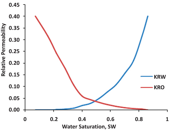 |
Fig. (7). Relative Permeability Curve. |
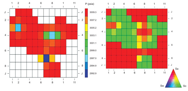 |
Fig. (8). Pressure and saturation distribution map of reservoir X. |
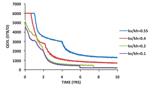 |
Fig. (9). Oil production rate. |
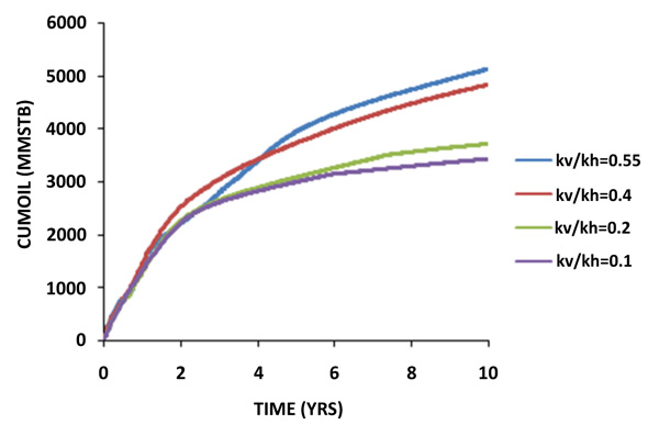 |
Fig. (10). Cumulative oil production. |
| Properties | Value |
|---|---|
| Reservoir area | 620 acres |
| Grid block size | 200ft x 200ft x 6ft |
| Top of Reservoir | 9290 ft |
| Water Oil Contact | 9330 ft |
| Reservoir thickness | 40 ft |
| Average Porosity | 0.22 |
| Initial Oil Saturation | 0.77 |
| Initial Water Saturation | 0.23 |
| Oil Viscosity | 2.4 cp |
| Water Viscosity | 0.96 cp |
| Oil FVF (Bo) | 1.175rb/stb |
| Water FVF (Bw) | 1.00325 rb/stb |
| Oil Density | 49.011 lb/cuft |
| Water Density | 62.140 lb/cuft |
| Water Compressibility | 3 x 10⁻⁶ psi-1 |
| Rock Compressibility | 3 x 10⁻⁶ psi-1 |
| Initial Reservoir Pressure | 4800 Psi |
| Bubble Point Pressure | 3000 Psi |
5.1. Influence of Vertical to Horizontal Permeability Anisotropy (kv/kh)
The effect of vertical to horizontal permeability anisotropy was analyzed by producing the reservoir with kv/kh varied at 0.1, 0.2, 0.4, and 0.55. A horizontal well was drilled at a length of 3000 ft and the simulator was run for 10 years. The results of the oil production rate and cumulative oil production are shown in Figs. (9 & 10).
Cumulative oil production appears to be increasing steadily as kv/kh ratio increases. From Fig. (10), kv/kh ratio of 0.55 predicted a higher cumulative oil production as compared to kv/kh ratio of 0.4, 0.2, and 0.1 at the end of the 10 years. This is because a low vertical to horizontal permeability anisotropy ratio minimizes the vertical cross flow of hydrocarbon between the layers of the reservoir.
Already conducted and validated studies by various researchers [22] on the effect of permeability anisotropy on horizontal well performance is in agreement with the findings of this research in the sense that their work depicted the same trend with this research work as shown in Figs. (9) & (10). In their work, kv/kh ratios of 1, 0.1, 0.0333, 0.02, and 0.01 were used to demonstrate that horizontal wells are more affected by anisotropy. The general trend observed from their results indicates that at higher kv/kh ratio, horizontal well perform better and as kv/kh ratio decreases, horizontal well productivity decreases. Also, in this present study, the results indicate that with the highest kv/kh ratio of 0.55, there was an increment in both oil production rate and cumulative oil production as compared to kv/kh ratio of 0.4, 0.2, and 0.1.
5.2. Horizontal Well Length Influence
At kv/kh of 0.55, the effect of horizontal well length was analyzed by producing hydrocarbon from the reservoir with a varied length of 1500ft, 2000ft and 3000ft. Running the simulator for 10 years, the results of the oil production rate and cumulative oil production with respect to time are shown in Figs. (11 & 12).
The results shown in Fig. (12) depict a uniform cumulative oil production from the three horizontal wells for the first two years. After the second year, cumulative oil production appeared to be increasing. However, horizontal well length of 3000 ft achieved the highest cumulative oil production at the end of the production period.
It was observed from the simulation studies conducted by Akpabio et al. [23] that increasing horizontal well length and production rate is desirable because it enhances ultimate recovery from the well bore. The findings of their research agree with this present study as depicted in Figs. (11 & 12). Considering horizontal well length of 3000 ft, 2000 ft, and 1500 ft, a higher oil production rate and cumulative oil production were obtained from horizontal well length of 3000 ft. The productivity of the horizontal well in this study shows a general increase with an increase in the well length. This is because, while the productivity of a horizontal well increases with an increase in well length, the efficiency of a horizontal well decreases with increases in the reservoir thickness [24].
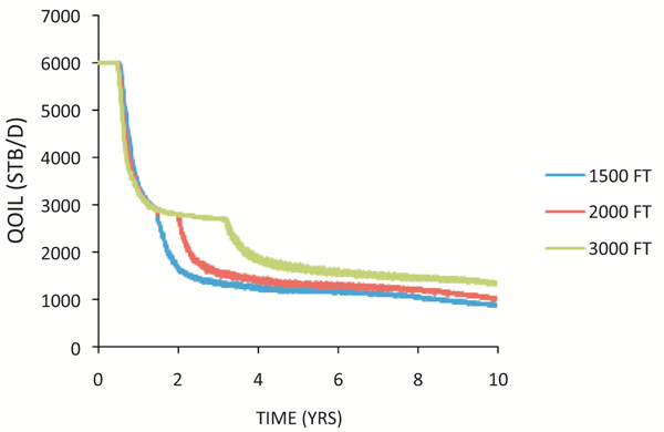 |
Fig. (11). Oil production rate. |
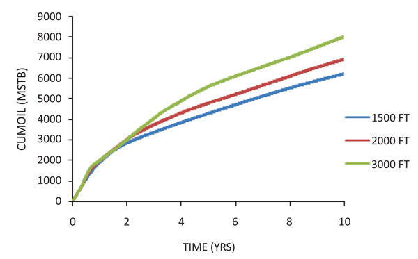 |
Fig. (12). Cumulative oil production. |
 |
Fig. (13). Water cut. |
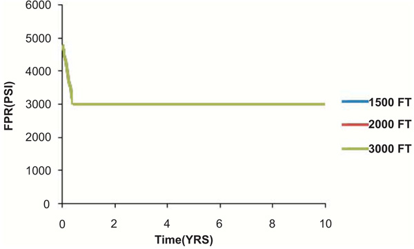 |
Fig. (14). Field pressure. |
Fig. (13) shows a graph of water cut versus time. Generally, the rate of water production from the reservoir was extremely low. This is because the analysis of the spatial distribution of petrophysical properties resulted in horizontal wells been drilled at best locations and perforated away from the water zone.
Fig. (14) shows a graph of field pressure versus time. The graph shows no significant variation in the field pressure for the three wells. At 3009 psi, the field pressure remained constant till the end of the production period, year 10. This is due to the presence of a strong aquifer which provided enough pressure support.
CONCLUSION
The study seeks to evaluate the performance of fully penetrated horizontal wells based on the analysis of spatial distribution pattern of the reservoir petrophysical properties. Geostatistical models of permeability, porosity, and thickness were used to populate the reservoir model for dynamic simulation. Based on the above analysis, the following conclusions were derived:
Vertical to horizontal permeability anisotropy ratio affects horizontal wells. The performance of the horizontal wells appeared to be increasing steadily as kv/kh increases. At a kv/kh value of 0.55, a higher cumulative oil production was observed compared to a kv/kh ratio of 0.4, 0.2, and 0.1.
In addition, horizontal well length significantly affects cumulative oil production of the petroleum reservoir. At kv/kh of 0.55, the results of the analysis showed a rapid increment in cumulative oil production as the length of the horizontal well increases. Considering horizontal well length of 3000 ft, 2000 ft, and 1500 ft, a maximum cumulative oil production was obtained from horizontal well length of 3000 ft.
CONSENT FOR PUBLICATION
Not applicable.
AVAILABILITY OF DATA AND MATERIALS
The data supporting the findings of the article is available in the [AAPG Datapages/Archives] at [http://archives. datapages.com/data/rmag/oilgasfields82/plumbushcreek.htm].
FUNDING
None.
CONFLICT OF INTEREST
The authors declare no conflict of interest, financial or otherwise.
ACKNOWLEDGEMENTS
The authors appreciate the All Nations University College (ANUC), Koforidua for the supports granted to complete this work.


