RESEARCH ARTICLE
Techno-Economic Comparison and Analysis of a Novel NGL Recovery Scheme with Three Patented Schemes
Kun Huang1, 2, Shuting Wang1, *, Muju Sun3, Luyao Tang3
Article Information

Identifiers and Pagination:
Year: 2017Volume: 10
First Page: 19
Last Page: 28
Publisher Id: TOPEJ-10-19
DOI: 10.2174/1874834101701010019
Article History:
Received Date: 22/07/2016Revision Received Date: 08/11/2016
Acceptance Date: 21/11/2016
Electronic publication date: 28/02/2017
Collection year: 2017
open-access license: This is an open access article distributed under the terms of the Creative Commons Attribution 4.0 International Public License (CC-BY 4.0), a copy of which is available at: https://creativecommons.org/licenses/by/4.0/legalcode. This license permits unrestricted use, distribution, and reproduction in any medium, provided the original author and source are credited.
Abstract
At present, most of the light hydrocarbons (LH) separation processes that have been proposed lack the flexibility of receiving various feed components, thereby leading to an unstable operation in the liquid natural gas (LNG) receiving terminal. In response, a novel light hydrocarbons separation process (PSP) is proposed in this paper. Previously, some parameters and processes were improved upon and patented as US 7165423 B2, US 7069743 B2, and WO/2012/054729, which are respectively named as LTP, NCP, and NLP. Based on the analysis of LNG’s component statistical data in China, this paper conducts a techno-economic comparison and analysis of four kinds of LH separation process under four groups of typical feed-in components. The comparison results reveal that the system energy consumption of LTP is increased by the heater, and the higher the heavy hydrocarbon content in the feed components, the more obvious the increase in the process’s energy consumption is. NCP has the highest ethane recovery rate; however, its capital cost is too high, especially for the distillation column investment. NLP has the highest operating cost due to compressor use. Compared to the others, the PSP has the best economic benefit for specific performance: its capital cost is 18% less than that of NCP, its operating cost is 71.8% less than that of NLP, its net profit is 8% higher than that of NLP, its total investment cost is 71.7% lower than that of NLP, and its investment recovery period is the shortest. In conclusion, the PSP can be economically and efficiently used in China LNG receiving terminal, thereby generating the flexibility to receive multiple feed components.
1. INTRODUCTION AND BACKGROUND
With the development of economic globalization, tremendous changes have taken place in energy structure. At present, China's energy consumption pattern is dominated by coal. The constraints on China's economic and social development and the impact on environment resources have become increasingly evident for this single structure [1]. In contrast, liquefied natural gas (LNG) as a clean and efficient green resource will be effective in optimizing the structure of China's energy.
In recent years, LNG in many international trades has been rich, changeable for composition, and contains more than 10% of hydrocarbons, except for methane (such as ethane, propane, and propane). Removing light hydrocarbons (LH) from the LNG plant will reduce LNG production as well as require additional compression devices. However, removing LH from the LNG receiving terminal can cause the receiving station to receive a variety of feed-in LNG from different suppliers, thereby improving the flexibility of LNG processing and meeting the requirements of LNG users. Moreover, C.C. Yang et al. insisted that it is a minor required change in typical LNG receiving terminal equipment, and no additional compression is required, and compared to a system that requires send-out gas compression or an inert-gas injection system to dilute the send-out gas, LH separation can reduce the capital investment by at least 40% and decrease operating costs [2]. In addition, ethane is a kind of high quality and clean raw material for ethylene production that has a high value. LH recovery can re-gasify LNG and produce ethane and liquefied petroleum gas (LPG) with low power consumption [3].
As early as 1960, the United States had a number of patents for the separation of LH from LNG. It is important to note that LH separation systems operate at higher operating pressures, which is not easy to transport and sell [4]. In 2003, Reddick et al. proposed a process for extracting natural gas condensate (NGL) from LNG [5]. The feed-in LNG for this process directly flows into the distillation column, which reduces the separation efficiency, and the pressure of the gas derived from the top of the column is increased by the compressor, which increases the process energy consumption. In 2005, Schroeder et al. proposed a LH separation process using LNG's own cold energy [6]. The heat exchanger is used to preheat the feed-in LNG to improve the fractionation efficiency of the methane removal tower; however, this process is limited by the use of a compressor that increases energy consumption. In recent years, the LH separation process has been deeply studied on the basis of energy saving and high efficiency. For example, Winningham in 2006 proposed a process for maximizing the use of a low temperature thermal performance of LNG, which reduced requirements for gas compression equipment [7]. Prim proposed a kind of LNG LH separation process with a feed-in LNG that flows into the demethanizer after two heat transfers, which is greatly simplified as compared with the previous process and completely avoids the use of a compressor [8]. On this basis, in 2012, PATEL et al. proposed a process that can produce both NGL and pure lean LNG products [9]. This process can adjust the operation mode according to the demands of pipe network quality and downstream users.
The above-mentioned LH separation processes lack the flexibility of receiving various feed components. They are characterized by complex processes, poor stability, and increased pressure from a compressor, which leads to high energy consumptions and low operation efficiencies in engineering practice. In addition, the use of ethane as a chemical raw material for ethylene production is hard to form in the downstream industry chain in China, and it is not easy to sell in North America and other international markets [3]. Therefore, this paper proposes a new LH separation process, based on the analysis of LNG component statistical data from around the world. Four groups of typical feed-in components are selected. Previously, some parameters and processes were improved upon and patented as US 7165423 B2, US 7069743 B2, and WO/2012/054729, and they were named as using LNG’s low temperature process (LTP), no compressor process (NCP), and producing NGL and LNG process (NLP), respectively. Thus, a techno-economic comparison can be made to the proposed LH separation process (PSP) that uses LNG’s low temperature and does not have a compressor.
2. DEFINITION OF FEED COMPOSITION AND MAIN MODEL
2.1. Definition of Feed Composition Based on Statistical Analysis
At present, China LNG resources are primarily supplied by Australia, Indonesia, Malaysia, Iran, Qatar, Papua New Guinea, Brunei, and others. There is no certain process or technique that is applicable to all the feed-in LNG components according to the principle of LH separation. Thus, in this paper, 130 groups of gas quality data of oil gas fields from around the world [10] and the feed components data of the LNG receiving terminal in China [11] have been studied. The probability distributions of methane, ethane, and propane are analyzed, respectively, and their corresponding normal distribution map is determined. Based on the high calorific value of the gas source in the Sichuan to East Gas pipeline, which is exactly 36.27 MJ/Sm3, four groups of typical components whose high calorific value is higher than the reference value are selected as the LH separation process feed data. The feed temperature, pressure, flow rate, and the thermodynamic model used for calculation are unified for simulation of the four LH separation processes. Typical feed composition and conditions for the LH separation process are listed in Table 1.
| Component/ mol% | Feed 1 | Feed 2 | Feed 3 | Feed 4 | |
|---|---|---|---|---|---|
| C1 | 95.94 | 89.32 | 85.28 | 78.9 | |
| C2 | 2.03 | 6.65 | 7.88 | 8.89 | |
| C3 | 0.81 | 1.51 | 2.53 | 2.78 | |
| i-C4 | 0.30 | 0.74 | 2.12 | 2.09 | |
| n-C4 | 0.41 | 0.81 | 0.71 | 2.10 | |
| i-C5 | 0.10 | 0.36 | 0.55 | 1.47 | |
| n-C5 | 0.10 | 0.4 | 0.37 | 1.78 | |
| C6 | 0.10 | 0 | 0.14 | 1.28 | |
| N2 | 0.20 | 0.21 | 0.42 | 0.36 | |
| Feeding Condition | |||||
| Pressure/kPa | 800 | Temperature /°C | -163 | ||
| Mass flow /(t•h-1) | 100 | Thermodynamic model | Peng-Robinson | ||
2.2. Product Requirements and Design Conditions of the Distillation Column
In this paper, the LH separation process that was studied in this paper only contains demethanizer. And not taking into account the effects of ethane products. The reasons for that contain:
a. Research was performed on the geographical position of the China receiving terminal, and it was found that the distance from the receiving terminal to the surrounding chemical refinery is not uniform.
b. The influence factors of the downstream industry chain of the ethane product are complicated, and it is not easily applied in practice.
In the simulation of four different LH separation processes, a unified outer transportation pressure of a natural gas product is set up. Because the operating pressure of the demethanizer is the main factor for determining the separation efficiency and energy consumption of LH separation, the four LH separation processes were carried out under different pressures (2~4.5MPa), and through such definition, the effects of the operation pressure and separation process on the separation efficiency and system energy consumption can be comprehensively analyzed and compared. The demethanizer simulation conditions of the four studied LH separation schemes are listed in Table 2. Where RE1″ and RE2″ stand for the feed position (from top to down) of the two streams of reflux liquids respectively for demethanizer in each schemes.
| Parameters | LTP | NCP | NLP | PSP | |
|---|---|---|---|---|---|
| Stage number | 16 | 30 | 11 | 15 | |
| Feed stage | Main feed | 6 | 18 | 1 | 1 |
| Reflux RE1″ | 1 | 1 | 6 | 6 | |
| Reflux RE2″ | 8 | — | 4 | 7 | |
| Overhead pressure /kPa | 2999 | 2103 | 4238 | 3000 | |
| Bottom pressure /kPa | 3034 | 2186 | 4273 | 3060 | |
| Constraints of column | Ethane mole fraction of overhead gas 0.0089%; Overhead gas flow 10000 kg/h |
Ethane mole fraction of overhead gas 0.0107% | Ethane mole fraction of overhead gas 0.0067% | Ethane mole fraction of overhead gas 0.0097% | |
3. CHARACTERISTICS ANALYSIS OF TYPICAL LH SEPARATION AND PROPOSED PROCESS
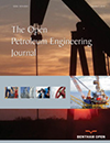
3.1. Using LNG’s Low Temperature Process (LTP)
The LH separation process proposed in Patent US 7165423 B2 [7] can handle the feed-in LNG with C2+ contents ranging from 2.5 mol% ~25 mol%. That improves the flexibility of the receiving terminal to receive various feeding, and its operation modes can be changed according to the requirements of product users, which are the high ethane extraction model (the level of ethane recovery ranges from 80% to 92%, and that of propane ranges from 90% to 95%) and the low ethane extraction model (the level of ethane recovery ranges from 1% to 2%, and that of propane ranges from 80% to 95%). In practical application, this model can flexibly change the proportion of ethane in the LNG product.
However, this method requires a small low-temperature compressor to increase the pressure of overhead gas that did not become completely liquefied to the downstream pipeline network output pressure owing to the heat transfer did not completely liquefied the gas. Although the volume flow of tail gas in this method is very small, compared to the consumptions of NSP that does not use compression equipment by heat transfer, the system energy consumption of the traditional process described in US 7165423 B2 [7] is still high. Therefore, this paper optimizes the parameters and process of the traditional process, which takes advantage of an LNG heat exchanger to reduce the temperature of the column overhead gas to below its bubble point temperature and completely liquefy it. It completely avoids the use of a tail gas compression device and LNG flash tank through a series of transformations, and the improved process is named as LTP. The LH separation process of LTP is shown in Fig. (1).
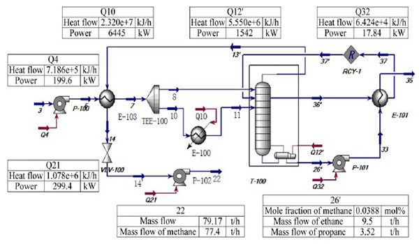 |
Fig. (1). HYSYS simulation chart for LTP. |
3.2. No Compressor Process (NCP)
The LH separation process, which is disclosed by Patent 7069743B2 US [8], contains three to four heat exchangers. The use of the heat exchange equipment avoids the extra refrigeration of the reflux liquid. This helps reduce the heat input of the distillation column and the system energy consumption with high ethane recovery rate. However, the NCP is limited by making use of a compressor to increase the pressure of rich methane gas, which leads to a raised energy charge. The LH separation process of NCP is shown in Fig. (2).
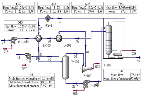 |
Fig. (2). HYSYS simulation chart for NCP. |
3.3. Producing NGL and LNG Process (NLP)
The LH separation process disclosed by Patent 2012054729A2 WO [9] has two operating modes: a high ethane recovery rate mode (99%) and high propane recovery rate mode (100%). This process can receive a variety of feed components, and has a wider C2 mole fraction receiving range of feed-in LNG (1%~50%) as compared to LTP. Furthermore, boosting the pressure of poor LNG to pipeline network pressure by compression equipment will increase the system energy consumption. Therefore, this paper optimizes the traditional process by using liquid lean LNG from the bottom of the separator as the condensed reflux liquid for the distillation column. After modification, the separation efficiency of the distillation column was obviously improved. The LH separation process of NLP is shown in Fig. (3).
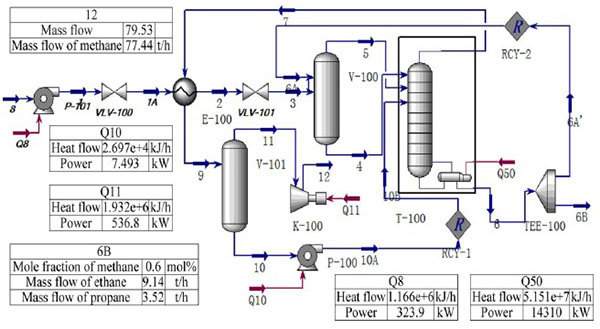 |
Fig. (3). HYSYS simulation chart for NLP. |
3.4. Proposed LH Separation Process (PSP)
The proposed LH separation process is inspired by the no compressor process (NCP); however, the process is greatly improved. This process is a twice cross heat exchange design that takes full advantage of the cooling energy by LNG and completely condenses the gas from the top of the distillation column without the use of compression equipments. Moreover, the proposed LH separation process has the notable advantages of low energy consumption and high separation efficiency.
The LH separation process of PSP is shown in Fig. (4). The feed LNG goes successively through the direct contact heat exchanger E-100, E-101, and heat transfer with, respectively, the methane rich gas from the top of the separator V-100 and the methane rich vapor from the top of the distillation column, and then, it flows into separator V-100 for gas-liquid separation. The liquid which mainly contains heavy hydrocarbon from the bottom of V-100 flows into the distillation column after being pumped. At the top of the separator, the methane rich gas, which is separated from the top of the separator, is pressurized to the operating pressure of the distillation column after the feed LNG is preheated. Part returns to the distillation column as the flux liquid, and the rest flows into the gasification unit. The system operates under 3~3.06 MPa. Additionally, a high concentration of methane vapor is obtained at the top of the distillation column, and it is completely liquefied after the feed LNG is preheated. After being pumped to the operation pressure of the distillation column, part returns to the distillation column as the flux liquid, and the rest flows into the gasification unit. The NGL which mainly contains heavy hydrocarbons is obtained in the bottom of the distillation column.
 |
Fig. (4). HYSYS simulation chart for PSP. |
4. TECHNO-ECONOMIC COMPARISON AND ANALYSIS
Aspen HYSYS was used to simulate four kinds of LH separation schemes in four kinds of feed components. Due to the change in feed components, different schemes have different economic benefits. In this paper, the Bare model is used [12], which is the most commonly used model to compare economic benefits [13], and its general equations are shown in Eq. (1) and Eq. (2). For the LNG receiving terminal, the fuel gas primarily comes from the boil off gas (BOG), which is provided from the BOG compressor. The NG products replace the BOG as the fuel source once the BOG does not meet the demand. Labor and sewage treatment costs are related to the local economic situation and other complex factors. Therefore, the annual profit objective function is determined as Eq. (2). The capital cost corresponds to the fixed equipment investment cost, and the operating cost corresponds to the water and electricity costs.
 |
(1) |
 |
(2) |
 |
(3) |
where P represents the annual profits, RMB/a. SG represents the natural gas sales, RMB/a. SNGL represents the natural gas liquid sales, RMB/a. CRM represents the fuel cost, RMB/a. COMd represents the capital cost, RMB/a. FCI represents the fixed equipment investment cost, RMB/a. COL represents the labor cost, RMB/a. CUT represents the water and electricity cost, RMB/a. CWT represents the sewage treatment cost, RMB/a. B represents the annual incomes, RMB/a. FCIˊ represents the capital cost, RMB/a. CUTˊ represents the operating cost, RMB/a.
4.1. Comparative Analysis of Energy Consumption
A comparative analysis was made between the energy consumption of PSP and the consumptions of LTP, NCP, and NLP, individually. The distillation column and the product external transport pump/compressor are the main energy consuming units in the LH separation process. The power comparison of the compressor/pumps and boilers of the four LH separation schemes are shown in Fig. (5).
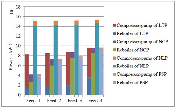 |
Fig. (5). Power comparison of the compressor/pumps and boilers of four LH separation schemes. |
The comparison results reveal that for one type of LH separation scheme, with an increase in the heavy hydrocarbon component in the feed LNG, the energy consumption of the boiler is increased. The LTP has a lower reboiler duty compared to the other schemes. This is because the heater in front of the distillation column provides an external heat energy to the distillation column so as to reduce the energy consumption of the distillation column. However, with an increase in the heavy hydrocarbon content in the feed LNG, the energy consumption of the process is obviously increased. Moreover, LTP has the highest energy consumption of the compressor/pumps and heaters. This is due to the high heavy hydrocarbon content in the distillation column’s siding. Additionally, in order to achieve the mass balance of C2 components and the corresponding heavy hydrocarbons in column rising steam, a large amount of overhead reflux is required to condensate the heavy hydrocarbons, which greatly increases the system energy consumption.
In contrast, for another type of LH separation scheme, with an increase in the heavy hydrocarbon component in the feed LNG, the energy consumption of the compressor/pump is decreased. The PSP has a lower compressor/pump duty as compared to the other schemes. This is because the cold energy of LNG is fully used to provide energy for the system to form a highly efficient thermal integrated network without using the compressor. The total energy consumptions of the NCP and PSP systems are relatively low, and NLP has the highest total energy consumption. However, the NCP is suitable for receiving a high heavy hydrocarbon content in the feed component because of the use of an external transport natural gas compressor. The energy consumption of the compressor is greatly increased once the feed component is relatively poor.
The flow rate comparison of the NGL product for the four types of LH separation schemes is shown in Fig. (6). The comparison results reveal that for one type of LH separation scheme, with an increase in the heavy hydrocarbon component in the feed LNG, the flow rate of the NGL product is increased. For the same feed components, the NGL production of the four schemes is basically the same, and the NCP has the highest NGL production. Because the reflux liquid is composed of the gas from the top of the distillation column for NCP, it is obvious that the reflux liquid mainly contains ethane and propane. The ethane and propane are absorbed in the column, and the heavier hydrocarbons (butane and heavier components) directly flow out from the bottom of the distillation column.
 |
Fig. (6). Flow rate comparison of NGL product for four types of LH separation schemes. |
4.2. Comparative Analysis of Capital Cost
A comparative analysis was made between the capital cost of PSP and the costs of LTP, NCP, and NLP, individually. The capital cost is primarily based on the cost of the main equipment in the process. In the capital cost estimation, the main process units are as follows: the distillation column, compressor, pump, heat exchanger, heater, and separator. The calculation data of the process equipment (the flow, temperature, pressure, and power) can be obtained by Aspen HYSYS. Based on this data, the capital cost estimation data have been studied.
The cost of the Bare model is the sum of the direct and indirect costs. The direct costs include the equipment, materials, and labor costs. The indirect costs include the freight, management, engineering, and other expenses. In accordance with the general chemical plant cost index (CEPCI=593.1) [14] and the annual cost of infrastructure cost formula [15] to establish a cost model, the capital cost analysis is carried out for the four types of schemes in the four kinds of feed components. A comparison of the total capital cost of each scheme is shown in Fig. (7). The results reveal that in the four feed components, the NLP and NCP have the lowest and the highest capital costs, respectively. This is due to the use of a compressor, which increases the pressure of most of the external transmission of natural gas. Although the distillation effect for NCP is superior to that of the other schemes, the numerous plates of the distillation column lead to a high investment cost.
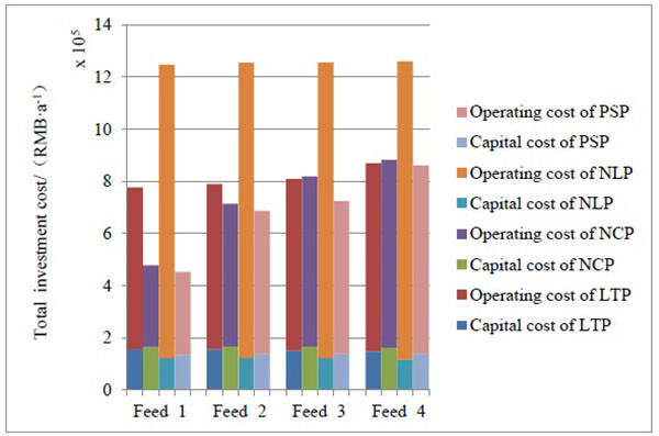 |
Fig. (7). Comparison of the total investment cost for four types of LH separation schemes. |
4.3. Comparative Analysis of Operating Cost
Operating cost estimates are often associated with a variety of complex factors, such as inflation, energy costs, and so on, which will cause fluctuations in energy prices [16]. Moreover, water and electricity costs and steam cost are also related to the energy supply and demand. Thus, it is quite difficult to calculate operating costs. Therefore, in this paper, the relative price is assumed to be a constant value in order to compare the operation cost of each LH separation process and different feed components.
A comparison of the annual operating cost for each LH separation process is shown in Fig. (7). The operating costs are two orders of magnitude higher than the capital cost; thus, it is difficult to adequately demonstrate the comparison in a single figure. In order to address this issue, the operating cost data are all multiplied by 0.01. It must be noted that, the reason why for that just in order to compare each cost with others, and the data of each process has not changed.
The comparison results reveal that for one type of LH separation scheme, with an increase in the heavy hydrocarbon component in the feed LNG, the operating cost is increased. This is because the condensation of heavy hydrocarbons in order to achieve a certain separation effect requires a high energy consumption. The operating cost of NCP is relatively lower; however, that of PSP is the lowest operating cost as compared to the other process. This is due to the use of heat exchangers in the process to replace the other high energy consumption equipment to provide the cooling capacity, thereby greatly reducing the system operating costs. In contrast, the NLP has the highest operating cost due to the use of a compressor to increase the pressure of the export natural gas.
4.4. Comparative Analysis of Total Investment
The total investment cost consists of the capital cost and operating cost [13]. A comparison of the total investment cost for each LH separation process is shown in Fig. (7). The comparison result reveals that the main decisive factor of the total investment cost is the operating cost, and PSP has the lowest total investment cost.
4.5. Comparative Analysis of Profit
The net profit and total investment cost are two important indicators to measure the quality of a process. The net profit is equal to the after tax annual income (25%) minus the total investment cost [13]. The investment recovery period is the ratio of the total investment cost and net profit. The comparison of the net profit for each process is shown in Fig. (8). And the net profit data for each process are shown in Table 3.
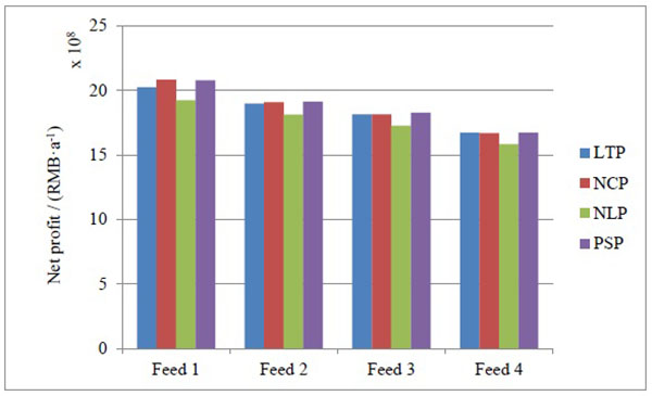 |
Fig. (8). Comparison of net profit for four types of LH separation schemes. |
| Net profit /RMB·a-1 | Feed 1 | Feed 2 | Feed 3 | Feed 4 |
|---|---|---|---|---|
| LTP | 2,022,736,843 | 1,897,593,739 | 1,815,828,068 | 1,673,592,781 |
| NCP | 2,081,770,756 | 1,907,257,505 | 1,814,045,718 | 1,667,667,883 |
| NLP | 1,924,085,745 | 1,811,073,222 | 1,725,990,225 | 1,584,162,353 |
| PSP | 2,077,195,211 | 1,913,007,760 | 1,827,340,573 | 1,673,341,444 |
The comparison result reveals that the PSP has the best economic benefit for specific performance: the net profit of PSP as compared to the other schemes is as high as 8%, its total investment cost is 71.7% lower than that of the other schemes, and its investment recovery period is also the shortest. In contrast, the NLP has the worst economic benefit, and the longest investment recovery period.
It is important to note that this paper carried out a simulation analysis based on Aspen HYSYS. The comparison of the estimated economic benefit is not based on the actual engineering application data, and the result data is only used as a reference for making comparison.
CONCLUSION
A novel LH separation process is proposed in this paper. Previously, some parameters and processes were improved upon and patented as US 7165423 B2, US 7069743 B2, and WO/2012/054729. Based on the analysis of LNG component statistical data in China, this paper conducts a techno-economic comparison and analysis of four groups of typical feed-in components. The comparison results reveal that:
- The system energy consumption of LTP is increased by the heater, and the higher the heavy hydrocarbon content in the feed components, the more obvious the increase of the process’s energy consumption is.
- NCP has the highest ethane recovery rate. However, its capital cost is too high, especially for the distillation column investment. NLP has the highest operating cost due to the compressor use.
- Compared to the others, the PSP has the best economic benefit for specific performance: its capital cost is 18% less than that of NCP, its operating cost is 71.8% less than that of NLP, its net profit is 8% higher than that of NLP, its total investment cost is 71.7% lower than that of NLP, and its investment recovery period is the shortest. In contrast, the NLP has the worst economic benefit and the longest investment recovery period.
In conclusion, the proposed novel light hydrocarbons separation process (PSP) can be economically and efficiently used in the China LNG receiving terminal, thereby generating the flexibility to receive multiple feed components.
CONFLICT OF INTEREST
The authors confirm that this article content has no conflict of interest.
ACKNOWLEDGEMENTS
We would like to thank Fei Xiao for his useful suggestions. We are also grateful to two reviewers for their critical review and constructive comments about the manuscript. We would also like to thank authors whose publications have not been listed in the references.