
RESEARCH ARTICLE
Study on Wellbore Stability of Shallow Sediments in Deepwater Drilling
Jun Zhang1, *, Chi Ai1, Bo Zeng2, Yuwei Li1, Jia Zeng1
Article Information

Identifiers and Pagination:
Year: 2017Volume: 10
First Page: 48
Last Page: 63
Publisher Id: TOPEJ-10-48
DOI: 10.2174/1874834101701010048
Article History:
Received Date: 10/11/2016Revision Received Date: 07/01/2017
Acceptance Date: 09/02/2017
Electronic publication date: 31/03/2017
Collection year: 2017
open-access license: This is an open access article distributed under the terms of the Creative Commons Attribution 4.0 International Public License (CC-BY 4.0), a copy of which is available at: https://creativecommons.org/licenses/by/4.0/legalcode. This license permits unrestricted use, distribution, and reproduction in any medium, provided the original author and source are credited.
Abstract
Background:
The deepwater shallow formation has low fracture pressure and narrow safe window of mud density, which results in a high risk of wellbore instability in this kind of formation.
Objective:
Without considering the plastic state of shallow formation around the borehole or the influence of in-situ stress difference on wellbore stability, the prediction accuracy of the traditional wellbore stability analysis models are relatively low. This paper can provide a reliable method to accurately predict the safe window of drilling fluid density.
Method:
In this paper, the shallow formation around the borehole is divided into plastic zone and elastic zone considering it under non-uniform in-situ stress. The collapse pressure formula of shallow formation is derived by taking the shrinkage rate of the borehole as the instability criterion. The fracturing pressure calculation model of shallow sediment under non-uniform in-situ stress is derived by combining the theory of excess pore pressure and hydraulic fracturing.
Conclusion:
The calculated results indicate that the horizontal in-situ stress difference has a significant effect on the shape of the plastic zone, the shrinkage rate of borehole, collapse pressure and fracturing pressure. The calculated results are in good agreement with the field test results, and the prediction accuracy of this model is higher than that of other traditional models.
1. INTRODUCTION
Marine oil and gas resources are very rich in the world, which is much more difficult to develop than in onshore oil field [1, 2]. Deepwater shallow sediment is less-consolidated and has high permeability and low strength. Because of its unique mechanical properties, the shallow formation around the borehole often has higher collapse pressure and lower fracture pressure. As a result, the narrow safe window of drilling fluid density usually causes the occurrence of drilling accidents [3-5].
Many studies have been conducted on wellbore stability of deepwater shallow sediments, for example, Wojtanowicz et al. established an elastic model which can reflect the mechanical characteristics of deepwater shallow sediment, and studied its fracturing pressure based on both theoretical analysis and numerical simulation [6]; R. Chhajlani and Z. Q. Zheng analyzed the stability of borehole wall in Mexico Bay deepwater oil field based on the linear elastic constitutive model and Mohr-Coulomb strength criterion and used the research results to guide the field work [7]. However, the traditional models of borehole wall stability analysis are based on elastic mechanics [8, 9]. Since the shallow sediment is similar to saturated soil, even if the stress around the borehole exceeds the rock strength, the borehole will remain stable and not collapse or fracture immediately. Therefore, the traditional analytical model cannot reveal the real borehole instability mechanism of deepwater shallow sediment. D. G. Ritter and B. Grollimund studied borehole stability in Brazil deepwater oil field based on the method of quantitative risk assessment, and the results showed that the prediction accuracy of in-situ stress and formation strength had the greatest influence on the analysis results [10]. E. Kaarstad and B. S. Aadnoy established an elastoplastic model for the fracturing pressure calculation of shallow formation based on the field data of deepwater drilling in Norway. But the empirical model based on field practice cannot truly reflect the actual stress state around the borehole [11, 12]. L. Yan et al. divided the shallow formation around the borehole into plastic zone and elastic zone and deduced the collapse pressure and fracturing pressure calculation formula based on the assumptions that the formation is in a uniform stress state and the plastic zone around the borehole is circular [13]. However, many researches and field tests showed that the horizontal stress difference has a significant impact on the collapse pressure and fracturing pressure although the horizontal stress difference in deepwater shallow formation is smaller than that in terrestrial formation. Therefore, the prediction accuracy of the calculation model under the assumption of uniform in-situ stress is relatively low.
In this paper, considering the shallow formation is in the condition of non-uniform in-situ stress and combining the rock mechanics and some theories of soil mechanics, the shallow formation around the borehole is divided into plastic zone and elastic zone. The formulas for calculating the plastic zone boundary and the shrinkage rate of the borehole under non-uniform in-situ stress are deduced by assuming that the stress-strain relation in the plastic zone is in accordance with the theory of large deformation. The shrinkage rate is chosen as the criterion of borehole collapse, and the collapse pressure formula of shallow formation is obtained. Then the fracturing pressure calculation model of shallow sediment under non-uniform in-situ stress is derived by combining the theory of excess pore pressure and hydraulic fracturing theory.
2. ESTABLISHMENT OF MECHANICAL MODEL
2.1. Characteristics of Deepwater Drilling and Wellbore Stability in Shallow Formation
Due to the lack of sufficient geological and logging data in deepwater drilling, the errors of calculation results of safety drilling fluid density window by the traditional models are always large. It is very important to establish a model to accurately predict the collapse pressure and fracture pressure of deepwater shallow formation. Although there are great differences in the physical and mechanical properties between the deepwater shallow sediment and the terrestrial formation, their research methods of borehole stability are same.
However, it is more difficult to analyze the wellbore stability in deepwater shallow formation. Firstly, overburden pressure of deepwater shallow sediment is lower than that of the terrestrial formation, which leads to a low fracturing pressure of shallow formation and a narrow safe window of drilling fluid density. Therefore, it is very important for deepwater drilling to improve the prediction accuracy of the safe window of drilling fluid density. Secondly, deepwater shallow formation is characterized by high porosity, high permeability, weak cementation and low strength, which is prone to transform into plastic state and appear as large deformation under the action of in-situ stress. In the process of drilling, some serious accidents often occur in shallow formation, such as wellbore shrinkage, drill pipe sticking and wellbore collapse. Thirdly, shallow formation may have shallow gas and shallow water, and well blowout or gas channeling is easy to occur. Because the shallow gas and shallow water can only be formed under special conditions, the first two problems are more important to evaluate the well bore stability in deepwater shallow formation.
2.2. Basic Assumptions and Mechanical Models
Deepwater shallow sediment is similar to saturated soil and can be considered as homogeneous, isotropic and ideally elastoplastic material. The traditional elastic model is relatively conservative in calculating the collapse pressure and fracturing pressure of shallow sediment. Many researches have proved that even if there is a certain plastic area appeared around the borehole in the shallow formation, the borehole wall can still maintain stability. Considering the effect of non-uniform in-situ stress, the mechanical model is established, as shown in Fig. (1). The shallow formation around the borehole is divided into elastic zone (E) and plastic zone (P). When borehole pressure (Pw) approaches the lower limit of the safe window of drilling fluid density, the formation around the borehole is in a plastic state. With the increase of borehole pressure, the formation is in gradual transition to the elastic state. But when borehole pressure continues increasing, the formation will turn back into the plastic state again. In Fig. (1), rw0 is bit radius during the drilling, mm; rw is the borehole radius after drilling, mm; rb is the distance elastic-plastic interface to the borehole center, mm; θ is angle from the orientation of minimum horizontal principal stress.
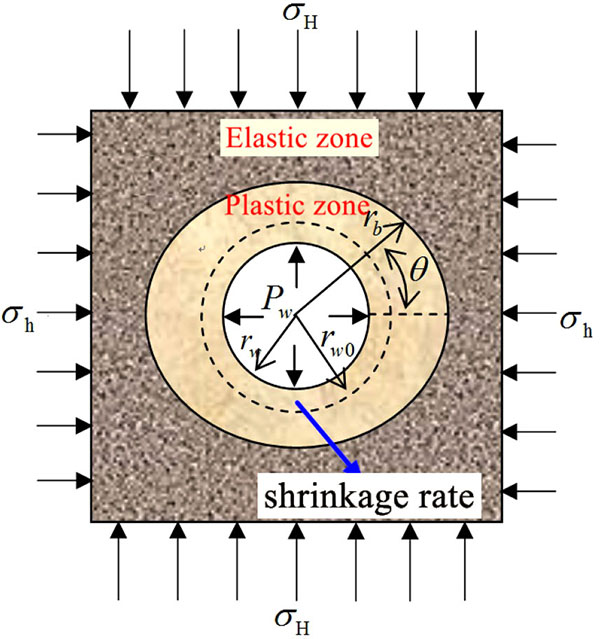 |
Fig. (1). Borehole mechanics model of shallow sediment. |
3. ELASTIC-PLASTIC INTERFACE OF MECHANICS MODEL
Deepwater shallow sediment has obvious plastic characteristics. When a borehole is drilled into the deepwater shallow formation, the stresses are redistributed around the wellbore. If the stresses exceed a yield criterion, a plastic zone can appear around the wellbore, which means that the shallow formation around wellbore experiences certainly a plastic stage before instability. Many studies have shown that the plastic zone boundary is not a standard shape of circle due to the non-uniformity of in-situ stresses [14, 15]. Fig. (1) shows the wellbore stress elastoplastic analysis model, where the approximate boundaries of the elastic zone and plastic zone are depicted. Based on the linear elastic theory, the stress distribution in the elastic zone around wellbore for shallow formation can be determined as follows [16-18]:
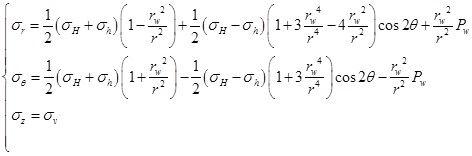 |
(1) |
Where σr and σθ are the radial and tangential stress.
Q. H. Sun et al. believe that the deepwater shallow formation in elastic zone is the ideal elastic material and obeys the Mohr Coulomb strength criterion [19]. It shows that Eq.(1) can be applied to the calculation of the stress in the elastic zone around wellbore for shallow formation. According to the study of B. H. Yu et al. [20], the shallow sediment around the borehole will turn into the plastic state after the formation of wellbore. There must be a transition point from the elastic zone to the plastic zone in the formation. Mohr-Coulomb criterion can be used to determine the boundary between the two zones [21]. According to the Mohr-Coulomb strength criterion, the yield function of deepwater shallow sediments is:
 |
(2) |
Where σθ and σr represent the minimum and maximum principal stresses, respectively N = (1 + sinθ) / (1 - sinθ), σ 0 = (2C cosθ) / (1- sinθ). C and φ are the cohesion and internal friction angle, respectively. σ0 is the uniaxial compressive strength (UCS), MPa.
Combining Eqs. (1) and (2), the distance of elastic-plastic interface from the borehole center(rb) can be written as:
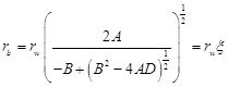 |
(3) |
Where
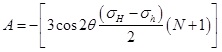 |
 |
 |
4. COLLAPSE PRESSURE CALCULATION MODEL
Deepwater shallow sediment is similar to saturated soil and has strong plasticity. When stress around the borehole exceeds the rock strength, the formation will turn into plastic state. In this case, the borehole will remain stable and not collapse immediately. The collapse pressure calculation model based on the elastic is relatively conservative. Therefore, considering the effects of borehole pressure, the balance equation can be established as:
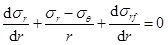 |
(4) |
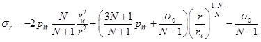
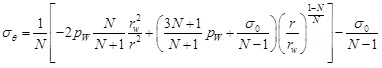
According to the Mohr-Coulomb strength criterion, the stress field in the plastic zone can be obtained by combining Eqs. (2) and (4). When σr|r = rw=Pw, the radial stress and tangential stress are:
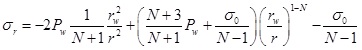 |
(5) |
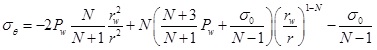 |
(6) |
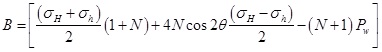
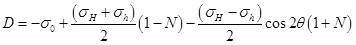
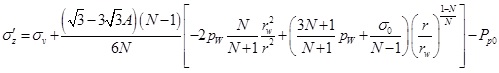
Substituting Eq. (3) into (5) and (6), the stress on the elastic–plastic interface are:
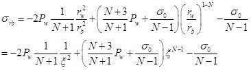 |
(7) |
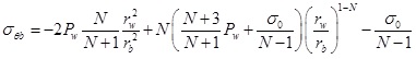 |
(8) |
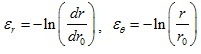
Many studies have shown that deepwater shallow sediment has a short diagenetic time. It is less-consolidated and has all physical properties of saturated soft soil [22, 23]. Therefore, the plastic zone around the borehole for shallow formation is controlled by the consolidation theory of saturated soil [24]. It is not suitable to analyze the stability of borehole wall with the traditional porous elastic theory because of the strong plasticity of shallow formation near the borehole wall. Y. Jin et al. have studied the borehole shrinkage deformation of salt gypsum formation and point out that the small deformation theory cannot describe the deformation law of the elastic-plastic formation, and the elastic-plastic deformation law of soft rock must be solved by large deformation theory [25]. The study of L. Yan et al. also suggests that the deformation of the plastic zone around the borehole for deepwater shallow sediment satisfies the large deformation theory. According to the large deformation theory, we can get the following formulas:
 |
(9) |
Where εr is the radial strain, εθ is the tangential strain; u is the formation displacement. Deepwater shallow sediment is similar to saturated soil which is undrained during the drilling, so the volumetric strain of the plastic zone is 0.
 |
(10) |
Assuming the displacement on the elastic-plastic interface is μb .
 |
(11) |
Zhou(2002) deduced the displacement field around borehole under uniform in-situ stress [26]. Considering the difference between maximum and minimum horizontal principal stress, the displacement on the elastic-plastic interface in non-uniform in-situ stress field can be written as
 |
(12) |
The displacement in the plastic zone can be obtained by substituting Eq. (12) into Eq. (11).
 |
(13) |
By substituting Eqs. (3) and (7) into (10), when r=rw, the borehole shrinkage rate of shallow sediments is obtained.
 |
(14) |
The collapse pressure calculation formula under the control of borehole shrinkage rate can be written as:
 |
(15) |
In deepwater shallow sediments, the borehole does not directly collapse. However, if the density of drilling fluid is too low, it will cause serious borehole shrinkage, which will influence wellbore stability and subsequent cementing operation. By (14) and (15), the shrinkage rate of borehole and the collapse pressure under the allowable shrinkage rate can be calculated. Many scholars have studied the collapse pressure of elastic-plastic formation on the basis of borehole shrinkage [27-29]. J.Q. Liu believe that when the stress state of the borehole wall exceeds the limit stress of the elastic-plastic formation, the formation of the surrounding rock will turn into the plastic state, which makes the radius of the borehole decrease continuously. When the borehole shrinkage rate reaches a critical value, the borehole wall will collapse [30]. Y. Jin et al. and Y. Yang et al. suggest that borehole shrinkage rate can be used as the borehole instability criterion for plastic formation [15, 31]. The above studies indicate that the collapse pressure calculation formula of deepwater shallow sediments under the control of different shrinkage rates is reasonable and appropriate.
5. FRACTURE PRESSURE CALCULATION MODEL
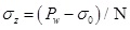
Different from terrestrial formation, the deepwater shallow formation around the wellbore will turn into plastic state before its fracturing. Shallow sediments are under the control of saturated soil consolidation theory. When the pore pressure is equal to the external pressure, the formation is under critical condition. The effective stress around the borehole will turn into a tensile stress if the pore pressure exceeds the critical value, and the formation will fracture if the tensile stress exceeds its tensile strength. At that time, the borehole pressure is the fracturing pressure. Therefore, the theory of excess pore pressure is introduced to analyze the changes of pore pressure.
5.1. Fracture Pressure of Vertical Fracture
When the borehole pressure exceeds the horizontal in-situ stress, radial stress on the borehole will be greater than the tangential stress and the borehole will turn into plastic state. When the vertical fracture appears on the borehole wall, the stress state on the borehole wall should be expressed as σr>σz>σθ. Thus, the yield function is:
 |
(16) |
 |
(17) |
Substituting Eq. (16) into Eq. (4), and when σr|r=rw=Pw, the tangential stress and axial stress in the plastic zone can be written as
 |
(18) |
 |
(19) |
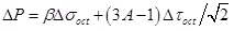
Shallow sediment is composed of solid particle skeleton and pores which are full of water. Drilling will result in stress concentration around the borehole, and the external pressure will cause a balance between effective stress and pore pressure. The pore pressure generated by external pressure is called excess pore pressure [32, 33]. The solution of excess pore pressure is mainly based on the researches of two scholars: Skempton and Henkel [34, 35]. Yan et al. combined their calculation model and rewrote the excess pore pressure formula as
 |
(20) |
 |
(21) |
 |
(22) |
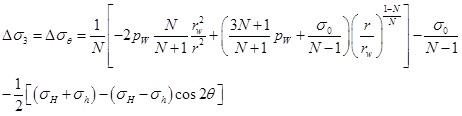
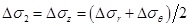
Where ΔP is the excess pore pressure. β is Henkel’s pore pressure parameters, for saturated soil, β=1. A is Skempton’s pore pressure parameter under the effect of deviatoric stress, for shallow sediments, A=0.8 [36, 37]. Δσ1 and Δσ3 are the major and minor principal stress increments.
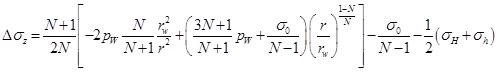
According to Eq. (18) and (19), the stress increment in plastic zone induced by drilling can be written as
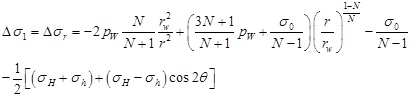 |
(23) |
 |
(24) |
On the basis of the plane strain theory, the axial stress increment in plastic zone around the borehole can be written as [38]:
 |
(25) |
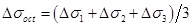
Substituting Eq. (23) and (24) into Eq. (25), the increment of axial stress in the plastic zone is obtained.
 |
(26) |
By substituting ΔσOCT and ΔτOCT into (20), the excess pore pressure in the plastic zone can be written as:
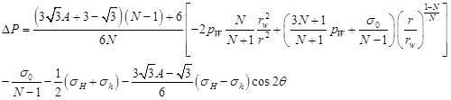 |
(27) |
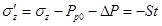
According to the effective stress principle, the effective stress in the plastic zone can be expressed as
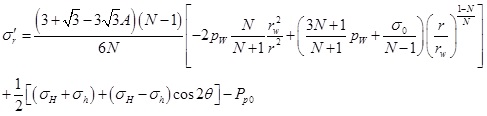 |
(28) |
 |
(29) |
 |
(30) |
Where Pp0 means the in-situ pore pressure.
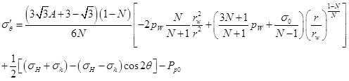
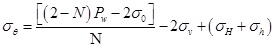
The above formulas indicate that the tangential and axial effective stress will increase with the increase of the radial distance. Therefore, the fracture appears on the borehole wall initially, which conforms to the general rule of borehole fracturing [39]. The tangential effective stress on the borehole wall is:
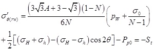 |
(31) |
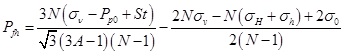
When the vertical fracture appears, the calculation formula of fracturing pressure can be written as:
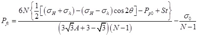 |
(32) |
5.2. Fracture Pressure of Horizontal Fracture
When the horizontal fracture appears, the stress state in plastic zone satisfies σr>σθ>σz. Therefore the yield function can be written as:
 |
(33) |
According to Eq. (25), the axial stress on the borehole wall can be obtained.
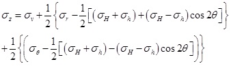 |
(34) |
Considering Eqs. (32) and (33), when σr=Pw, the tangential and axial stress of the wellhole can be expressed as
 |
(35) |
 |
(36) |
Then the excess pore pressure is obtained:
 |
(37) |
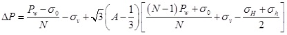
When the fracture appears on the borehole wall, the tangential effective stress should meet Eq. (39).
 |
(38) |
When the horizontal fracture appears, the calculation formula of fracturing pressure can be written as:
 |
(39) |
The minor value of these two above fracturing pressures ought to be regarded as the fracturing pressure of shallow sediments (Pf):
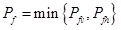 |
(40) |
6. CASE STUDY
In order to verify the theoretical model proposed in this paper. The data of wells in a block from the South China Sea are used to case study. The physical and mechanical parameters of the formations are shown in Table 1.
| Well number | Depth /m |
σv /MPa |
σH /MPa |
σh /MPa |
C /MPa |
φ /deg |
E /MPa |
v |
Pp0 /MPa |
|---|---|---|---|---|---|---|---|---|---|
| 1 | 3230 | 25.1 | 25.5 | 24.7 | 0.22 | 4.9 | 286 | 0.37 | 20.7 |
| 2 | 3453 | 26.3 | 27.1 | 25.8 | 0.25 | 4.8 | 312 | 0.41 | 21.8 |
| 3 | 3357 | 25.7 | 26.7 | 26.2 | 0.29 | 4.4 | 307 | 0.38 | 22.1 |
6.1. Boundary of Plastic Zone and Shrinkage Rate of Borehole
The boundary of plastic zone and borehole shrinkage rate are calculated and analyzed based on the parameters of Well-1. σh is kept constant and σH is gradually increased, then the variation of the plastic zone boundary and the borehole shrinkage rate under the condition of different horizontal stress difference is obtained. From Fig. (2) we can see that the horizontal stress difference has a significant impact on the shape of the plastic zone. The plastic zone is a circular under the uniform in-situ stress, and with increase of horizontal stress difference, the plastic zone gradually changed into an ellipse. Fig. (3) shows the variation rule of borehole shrinkage rate. Many scholars believe that the borehole shrinkage rate is a fixed value, that is, the degrees of shrinkage in different directions are different. However, the calculation results in this paper show that the borehole shrinkage rate changes with θ under the non-uniform in-situ stress. With the increase of horizontal stress difference, the anisotropy of borehole shrinkage rate increases. In Fig. (3), when the horizontal stress difference reaches 2.5MPa, the borehole shrinkage rate in the direction of σH is 0.87, and that in the direction of σh is 2.13. Based on Ewy’s criterion [40], when the borehole shrinkage rate exceeds 2%, it will influence the safety of drilling. According to this criterion, the borehole wall in the direction of σh has collapsed, but the borehole wall in the direction of σH remains stable. It is proved that the anisotropy of in-situ stress has a significant influence on the stability of borehole wall.
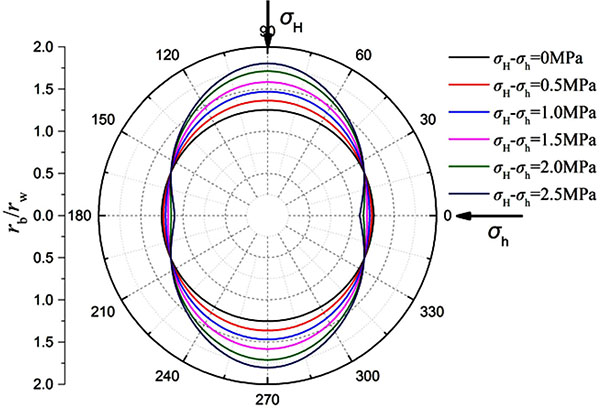 |
Fig. (2). Plastic zone boundaries under different horizontal stress difference (Well-1). |
 |
Fig. (3). Shrinkage rates of borehole under different horizontal stress difference (Well-1). |
6.2. Collapse Pressure
First, the collapse pressures under different horizontal stress difference are calculated based on the based on the parameters of Well-1. It can be seen from Fig. (4) that there is a significant difference in the collapse pressure in different directions under non-uniform in-situ stress. With the increase of horizontal stress difference, the difference of collapse pressure in different directions increases gradually. Therefore, it is not appropriate to consider the formation in a uniform in-situ stress state in the evaluation of wellbore stability for deepwater shallow formation. Then, the collapse pressures of three wells are calculated. In Fig. (5), curves a, b and c represent the calculated collapse pressures of three wells, respectively. Under a 2% hole shrinking rate, the collapse pressures of three wells change periodically with θ. Take curve a as an example, collapse pressures of Well-1 are 18.4MPa and 21.1MPa in the direction σh and σH, respectively. Therefore, the collapse pressure of shallow sediments is 18.4MPa. At this depth, the pore pressure after drilling is 20.07 MPa, which is greater than the calculated collapse pressure. Through further calculation, the borehole shrinkage rate is about 1.4%, which there was no drilling accident. The field data and test result also indicated that the drilling process is safe. The calculation results of another two wells are also in agreement with the actual measured values, which verifies the accuracy of the model established in this paper.
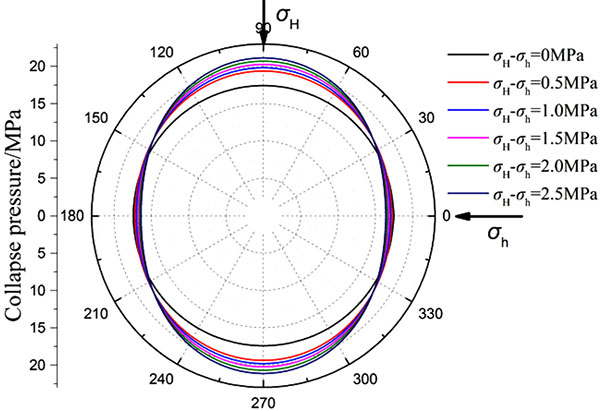 |
Fig. (4). Collapse pressures under different horizontal stress difference (Well-1). |
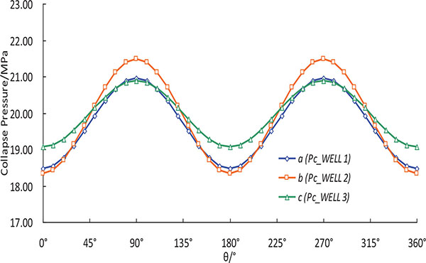 |
Fig. (5). Variation of calculated collapse pressure with the angle θ. |
(a: collapse pressure of well 1,b: collapse pressure of well 2,c: collapse pressure of well 3)
6.3. Fracture Pressure
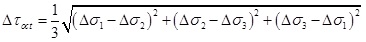
Fig. (6) shows the calculation results of the fracturing pressure under different horizontal stress difference (Well-1). Pfv exhibits periodic variation with θ, which indicates that the horizontal stress difference has a significant impact on Pfv. The difference of Pfv in different directions increases with the increase of the horizontal stress difference. However, Pfh is independent of θ and not affected by the horizontal stress difference. For Well-1, Pfh is always less than the minimum of pressure Pfv, which indicates that the borehole wall of Well-1 at this depth should generate vertical fracture. In order to further verify the reasonability of the proposed model for calculating the fracturing pressure of shallow formation, the fracturing pressures of three wells are calculated. As shown in Table 2, the results are compared with the calculation results of the traditional model: elasto-plastic fracture model of Aadnoy (2004) and shallow sediment model of Kaarstad (2008). The actual measured fracture pressure was obtained from leak off tests (LOT). As shown in Table 2, the calculation results by Kaarstad’s model have a large deviation from the actual measured values, which is due to the fact that Kaarstad’s model belongs to the empirical model and does not consider the plastic state of shallow formation around the borehole. The Aadnoy’s model is based on the assumption that the fracture occurs first on the elastic–plastic interface. The calculated fracturing pressure of this model is much higher than the result of the elastic model, which is not consistent with the fact that the deepwater shallow formation has a low fracturing pressure. The error between the results of this model and measured values is also large. Besides, Aadnoy’s model indicates that when the borehole in shallow formation is broken, only horizontal fracture can be formed on the borehole wall, but no vertical fracture can be formed. But the field data show that the shallow sediment of these three wells all generate vertical fracture, which also proves the limitations of Aadnoy’s model. The error of fracture pressure calculated by the model established in this paper is the lowest, and it is mostly in agreement with the actual measured values, which verifies the accuracy of the model established in this paper. It also proves that the consideration of the influence of non-uniform in-situ stress and the introduction of excess pore pressure theory in the analysis of fracture mechanism in deepwater shallow sediments is feasible.
| Well | LOT results /MPa |
Results of model in this paper | Results of Aadnoy’s model | Results of Kaarstad’s model | ||||||||
|---|---|---|---|---|---|---|---|---|---|---|---|---|
| Pfv /MPa |
Pfh /MPa |
Pf /MPa |
Error /% |
Average | Pf /MPa |
Error /% |
Average | Pf /MPa |
Error /% |
Average | ||
| 1 | 28.25 | 28.66~31.11 | 34.21 | 28.66 | 1.5 | 2.1 | 30.41 | 7.6 | 7.4 | 26.78 | 5.2 | 6.3 |
| 2 | 27.34 | 26.95~33.40 | 33.73 | 26.55 | 2.7 | 29.68 | 8.5 | 26.19 | 4.2 | |||
| 3 | 29.32 | 28.98~32.86 | 33.29 | 28.68 | 2.1 | 27.55 | 6.0 | 26.55 | 9.4 | |||
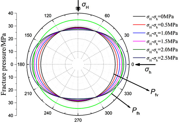 |
Fig. (6). Fracturing pressures under different horizontal stress difference(Well-1). |
6.4. Borehole Stability Analysis
In order to further analyze the particularity of wellbore stability in deepwater drilling, the borehole stability of Well-2 in the shallow formation is evaluated according to the field data. Field data show that the density of shallow formation is very low, and the mud density is about 1.1 g/cm3. Together with the impact of the upper sea water, the overburden pressure of deepwater shallow formation is very low, which is 0.7 g/cm3 smaller than that of terrestrial formation at the same depth. As shown in Fig. (7), the pressure system of the well is normal, and the water depth has no effect on the formation pressure. The horizontal stress of this well is low, and there are some differences between the two horizontal principal stresses. The safe window of drilling fluid density of shallow formation is narrow and the fracturing pressure is very low. If the minimum horizontal stress is selected as leakage pressure, the density window between leakage pressure and collapse pressure is approximately 0.3 g/cm3, which indicates that the leakage of mud is easy to occur during drilling, so it is necessary to enhance the sealing property of drilling fluid. In order to avoid instability of borehole wall caused by surge pressure, the drilling technology should be optimized based on the reasonable selection of drilling fluid density. The calculated value of collapse pressure is consistent with the practical drilling fluid density, and the fracturing pressure is consistent with the measured value, which shows the reliability of the calculation model proposed in this paper.
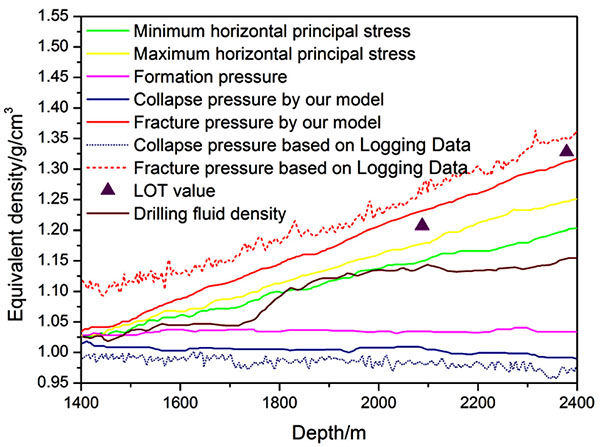 |
Fig. (7). Safety density window of drilling fluid in deepwater shallow sediment (Well-2). |
The total depth and water depth of the Well-2 are 3453m and 1367m, respectively. The lithology of the target formation is mainly the interbeds of gray fine sandstone and gray mudstone in different thickness. The actual drilling fluid density in the shallow formation is 1.03~1.15g/cm3. Caliper logging data show that the borehole shrinkage rate of Well-2 in the shallow formation is 0.68~1.35%. During the process of drilling, there is no borehole wall collapses. At the drilling depth of 2079m and 2382m, leak off tests were carried out. The error analysis of the measured value of fracture pressure and the results of this paper are shown in Table 3. The prediction accuracy of each test point is more than 90%, which can meet the requirements of engineering construction. The results indicate that the safe drilling fluid density window based on the model in this paper is reliable. The collapse pressure and fracture pressure of the Well-2 are also calculated by using seismic velocity data, as shown in Fig. (7) (dotted lines). Compared with the calculated results based on the logging data, the drilling fluid density window calculated by the model in this paper is narrower and more close to the measured values, which proves that wellbore stability analysis in this paper is accurate and has an important guiding significance for the subsequent deepwater drilling.
| Depth of Well-2 /m | Equivalent density of measured fracture pressure (LOT)/g.cm-3 | Equivalent density of fracture pressure obtained in this paper /g.cm-3 | Error /% |
|---|---|---|---|
| 2079 | 1.21 | 1.24 | 2.5% |
| 2382 | 1.33 | 1.31 | 1.5% |
CONCLUSION AND SUGGESTIONS
- The difference of horizontal in-situ stress in deepwater shallow formation is smaller than that in terrestrial formation. But the shallow formation is similar to the saturated soil, so even a small in-situ stress difference can significantly affect the deformation law of formation around borehole. Therefore, it is inappropriate to assume the formation under uniform in-situ stress in the analysis of wellbore stability of shallow formation. The results in this paper indicate that the shape of the plastic zone is very sensitive to the horizontal stress difference. The plastic zone is elliptical under non-uniform in-situ stress, and the area of plastic zone decreases with the increase of borehole pressure.
- In deepwater drilling, if the mud density is low, the borehole will shrink before it collapses. When the shrinkage rate reaches the critical value, the borehole begins to collapse. The shrinkage rate of borehole is not a constant value under the non-uniform in-situ stress, but varies with θ. The calculation formula of collapse pressure under the control of borehole shrinkage rate is obtained. The results indicate that the horizontal stress difference has a significant effect on the collapse pressure of shallow sediment, and the minimum collapse pressure is in the direction of horizontal principal stress.
- The fracturing pressure calculation model of shallow sediment under non-uniform in-situ stress is derived by combining the theory of excess pore pressure and hydraulic fracturing theory. The calculated results show that when the borehole in shallow sediment generates the vertical fracture, the fracturing pressure is not a constant value, but varies with θ. In this case, the fracturing pressure has the minimum value in the direction of the maximum principal stress. When the borehole generates the horizontal fracture, the fracturing pressure is independent of θ. The minimum value of these two kinds of fracturing pressure can be considered as the fracturing pressure of shallow formation.
- Case study indicate that the results calculated by the proposed model in this paper are very close to the actual measured values, which prove the reasonability of the basic assumptions and reliability of the calculated results. Considering the deepwater shallow formation is under non-uniform in-situ stress, according to the calculation model of this paper, minimum values of fracturing pressure and collapse pressure should be the safe upper limit and lower limit of drilling fluid density, respectively. This paper can provide a reliable method to accurately predict the safety window of drilling fluid.
LIST OF SYMBOLS
| σH | = Maximum horizontal principal stress, MPa |
| σh | = Minimum horizontal principal stress, MPa |
| Pw | = The borehole pressure, MPa |
| rw0 | = Bit radius during the drilling, mm |
| rw | = Borehole radius after drilling, mm |
| rb | = Distance elastic-plastic interface to the borehole center, mm |
| θ | = Angle from the orientation of minimum horizontal principal stress, deg |
| σr | = Radial stress on the wall of borehole |
| σθ | = Tangential stress on the wall of borehole |
| C | = Cohesion, MPa; |
| φ | = Internal friction angle, deg |
| σ0 | = Uniaxial compressive strength (UCS), MPa |
| εr | = The radial strain |
| εθ | = The tangential strain |
| u | = Is the formation displacement |
| μb | = Displacement on the elastic-plastic interface |
| μrb | = Displacement on the elastic-plastic interface |
| ΔP | = Excess pore pressure, MPa |
| β | = Henkel’s pore pressure parameters, for saturated soil, β=1 |
| A | = Skempton’s pore pressure parameter under the effect of deviatoric stress |
| Δσ1 | = Major principal stress increments |
| Δσ3 | = Minor principal stress increments |
| Pp0 | = In-situ pore pressure, MPa |
| Pc | = Collapse pressure of shallow sedimentary formations, MPa |
| Pfv | = Fracture pressure of vertical fracture, MPa |
| Pfh | = Fracture pressure of horizontal fracture, MPa |
| Pf | = Fracture pressure of shallow sedimentary formations, MPa |
CONFLICT OF INTREST
The authors confirm that this article content has no conflict of interest.
ACKNOWLEDGEMENTS
This work was supported by the National Science and Technology Major Project of China (2016ZX05046004-004) and National Natural Science Foundation of China (No.51490650).