
RESEARCH ARTICLE
Analysis of the Cutting Features of the Damaged Rock by Shock Disturbance
Lou Lei, Wu Wanrong*, Liang Xiangjing
Article Information
Identifiers and Pagination:
Year: 2016Volume: 9
First Page: 159
Last Page: 168
Publisher Id: TOPEJ-9-159
DOI: 10.2174/1874834101609160159
Article History:
Received Date: 29/12/2015Revision Received Date: 31/03/2016
Acceptance Date: 12/06/2016
Electronic publication date: 26/08/2016
Collection year: 2016
open-access license: This is an open access article licensed under the terms of the Creative Commons Attribution-Non-Commercial 4.0 International Public License (CC BY-NC 4.0) (https://creativecommons.org/licenses/by-nc/4.0/legalcode), which permits unrestricted, non-commercial use, distribution and reproduction in any medium, provided the work is properly cited.
Abstract
This article aims to study the effects of shock-disturbed cracks on the cutting features of cone bits. By utilizing the Walsh’s model, a crack model was established for the damaged rock surrounding the induced hole, the intrusive coefficient of the cone bit was derived, and the drilling rate equation around the induced hole was formulated. The effects of crack density and disturbance frequency on elastic modulus, intrusive coefficient, and cutting force were studied. With an increase in crack density, both the effective elastic modulus and the intrusive coefficient decreased. Under a certain range of internal friction angle, with an increase in crack density, the drilling rate increased. Under a certain axial load, as the disturbance frequency increased, the cutting force of one-cone bits decreased.
1. INTRODUCTION
Large diameter rotary drilling rigs are inefficient and their cone bits suffer serious wear when used in hard rock drilling. To address this drawback, the new technology of shock-induced drilling is presented, and the principle is shown in Fig. (1). The strength of the rock mass is weakened by the redistribution of stress around the induced hole, thereby simplifying the cutting of rock mass in damaged zones [1-3].
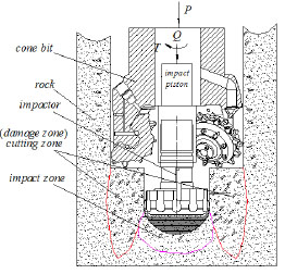 |
Fig. (1). Principle of drilling by shock induced. |
Drilling engineering is primarily concerned with the study and application of the cone bit drilling rate equation, because drilling efficiency directly influences drilling progress and cost [4, 5]. The shock-induced drilling rate of cone bits is related to bit structural parameters, rock parameters, and shock frequency [6, 7]. A reasonable equation of the cone bit can predict the drilling rate and provide guidance for field drilling [8-10]. A tool-damaged rock model and a damaged rock-crack model should be constructed to examine the cutting features of damaged rocks. Walsh’s model was revisited and extended by considering the stress of cracks under the loading and unloading process [11]. However, David’s study did not consider the effect of disturbance frequency on the cracks. Li Wei et al. [12-14] performed laboratory rock breaking experiments to examine the effects of structural parameters on the drilling rate and established the cone bit drilling rate equation. A new rate of penetration (ROP) model of rollercone bits is developed by Rashidi [15, 16], which can be used to predict the ROP of the cone bit and generate accurate rock strength values. However, Li’s study and Rashidi’s model did not consider the effect of crack density on the equation.
In the present paper, the effects of cracks on the elastic modulus are analyzed in detail (cracks are produced by the impactor in the damage rock). The influences of different densities and orientations of cracks on the drilling rate are evaluated. Finally, the effects of cracks on the cutting force at different disturbance frequencies are examined.
2. SHOCK-INDUCED DRILLING
The principle of shock-induced drilling is shown in Fig. (1). First, the impactor was used to drill the center hole; the strength of the rock mass is weakened by the redistribution of the stress around the induced center hole. Second, the low cutting force on the damage zone can crush the rock. P is the axial pressure, Q is the impact load, and is the rotary torque.
Fig. (2) is the force analysis diagram of the damaged rock around the induced hole during tooth intrusion. r0 is the radius of the induced hole, r is the radius of the tooth intrusion, r1 is the radius of the cone bit, r1-r0 is the radius of the weakened zone of rock around the induced hole, L is the distance between the cone bit’s tooth and the impactor’s tooth. Fig. (3) [11, 13] is the enlarged image of region C in Fig. (2).
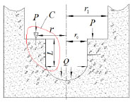 |
Fig. (2). Force analysis of rock around the induced hole during tooth intrusion. |
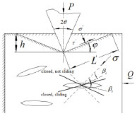 |
Fig. (3). Enlarged image of region C in Fig. (2). |
3. MATHEMATICAL MODEL OF DAMAGE ZONE
3.1. Effect of Cracks on Elastic Modulus
Fig. (3) shows the forces for the damaged rock under the drilling tooth. In Fig. (3), σ' and τ' are the normal and the shear stresses on the failure surface respectively, θ is tooth blade angle, h is the intrusion depth, L' is the length of the failure surface, βc is the critical angle of closed, βs is the critical angle of sliding, φ is the angle between failure surface and horizontal plane. If the damaged rock contained N independent elliptical cracks, the elliptical crack’s half-length is c and it would be subjected to force σ:
 |
(1) |
The dimensionless functional relationship between the macroscopic and the microscopic parameters can be expressed as follows [17]:
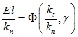 |
(2) |
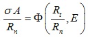 |
(3) |
where E is the elastic modulus of the undamaged rock, l is a certain length parameter, kn and kt are the contact stiffness in the normal and tangential direction, respectively, A is the characteristic area, Rn and Rt are the interface strength in the normal and tangential direction, respectively.
Assuming that σc is the stress which causes the crack face contact, then the normalized stress can be defined as follows:
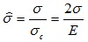 |
(4) |
If σ̂ < 1, a crack at any orientation would be open, so the elastic modulus can be expressed as follows:
 |
(5) |
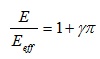
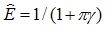
where γ is the crack density parameter, and Eeff is the effective modulus. If the normalized elastic modulus is defined as, Ê = Eeff / E then the normalized modulus of the damaged rock containing randomly open cracks, N, would be expressed as:
 |
(6) |
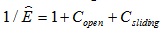
If σ̂ < 1 and β > βc, the cracks would be open; If σ̂ < 1 and β > βc, the cracks would be closed. The closed crack would be sliding if βc < β < βs, and would not be sliding if βs < β < π/2. The said situation is illustrated in Fig. (3). The normalized elastic modulus under the condition of loading is:
 |
(7) |
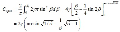
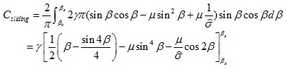
where Copen and Csliding are the compliance of the open cracks and the sliding cracks, respectively; their values can be expressed as:
 |
(8) |
 |
(9) |
Under the impact load Q, the applied compressive axial stress is assumed to increase to a certain value σmax, then the value would begin to decrease. The decrease of the compressive stress can be considered as a tensile stress. If the value of the applied stress is reduced to a certain value σ = σmax - Δσ, the shear stress would produce the relevant decreased Δτ on the crack, meanwhile the frictional resistive stress will decrease Δτf. The condition of the reverse sliding is:
 |
(10) |
Therefore, the condition of the reverse sliding can be expressed as:
 |
(11) |
where βrs is the critical angle of the reverse sliding.
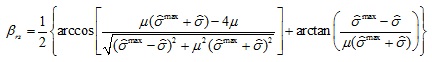 |
(12) |
The contribution of the cracks on the compliance would be given by
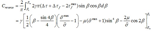 |
(13) |
The expression of the normalized modulus under the stage of unloading is now given by
 |
(14) |
3.2. Drilling Rate of the Cone Bit on the Damaged Rock
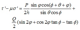
As shown in Fig. (3), the normal stress σ' `and the shear stress τ' could be expressed as:
 |
(15) |
 |
(16) |
The damaged rock around the induced hole will be crushed if:
 |
(17) |
where C is the cohesion of the rock without cracks, C' is the cohesion of the rock with cracks, and ϕ is the angle of the friction. The related equations are substituted into (17), then:
 |
(18) |
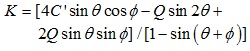
where µ is the internal friction coefficient, the intrusion depth of the tooth is:
 |
(19) |
where K is the intrusion coefficient,
 ,the cone bit drilling rate equation is:
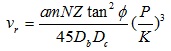 |
(20) |
where vr is the cone bit drilling rate, a is the coefficient of the tooth, m is the number of tooth, N is rotated speed, Z is the number of the tooth’s ring, Db is the diameter of the cone bit, and Dc is the diameter of the cone.
4. SIMULATION AND TEST RESULTS
The bonded particle model of the rock material was built in the particle flow code software (PFC2D). Because the particle flow samples can reflect the macroscopic mechanical properties of real rock materials, calibrating the microscopic parameters of the particle model was necessary. The rock material in this study was granite purchased from Yuelu Mountain in Hunan province. The set of microscopic parameters of the simulation is:
Rn = 150 N , Rt = 121 N , kn = kt = 3.6 x 10⁶N / m, µ = 0.5. Table 1 shows the comparison of the simulated values and the macro parameters of the real rock material. The error between the simulated values and the real values is very small. The simulated system is shown in Fig. (4).
 |
Fig. (4). The numerical simulation system. |
The experimental system is shown in Fig. (5). Fig. (5a and b) shows the experimental principle and the experimental system, respectively. The specimen size is 400 mm x 400 mm x 500 mm (length x width x height). Before the test, the surface of the specimen is polished by a grinder. The induced hole is then drilled with the impactor at different frequencies 0, 15, and 30 HZ. The diameter of the center hole is 100 mm and the depth of the hole is 400 mm. Then the specimen is pushed to the right place by the oil cylinder. Finally, the cutting force of a single cone bit around the center hole was tested under the same axial loads. The simulated and experimental results are shown in Figs. (6-9).
 |
Fig. (5). (a) The experimental principle, (b) The experimental system. |
 |
Fig. (6). Cracks’ propagation conditions of the region A in Fig. (4) under different disturbance frequencies (a) 0HZ, (b) 5HZ, (c) 10HZ and (d) 15HZ. |
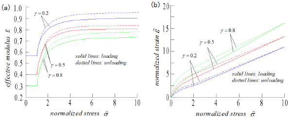 |
Fig. (7). (a) Curves between Normalized effective modulus and the normalized stress, (b) Curves between normalized strain and normalized stress. |
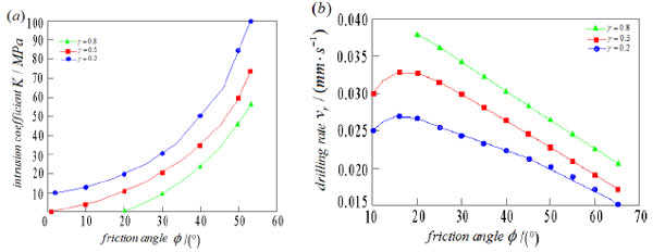 |
Fig. (8). (a) Curves between intrusion coefficient and the friction angle, (b) Curves between the drilling rate and the friction angle. |
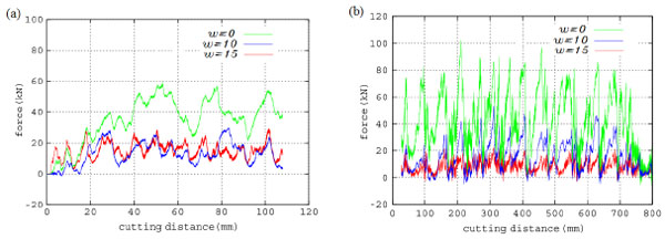 |
Fig. (9). Comparison between simulation and the experimental results of the cutting force at different disturbance frequency (a) Simulated results, (b) Experimental results. |
When the disturbance force is constant, the cracks of the region A in Fig. (4) under the condition of different disturbance frequency, shown in Fig. (6). Fig. (6a-d), are the cracks’ propagation conditions of the region A under the condition of 0, 5, 10 and 15 HZ. In contrast to Fig. (6), the cracks of the region A increased as the disturbance frequency increased. This shows that the elastic modulus of the granite decreased with the increase of the disturbance frequency.
| Mechanics Property | Elastic Modulus/ GPa |
Poisson Ratio |
Tensile Strength /MPa |
Compression Strength/MPa | Cohesion /MPa |
|---|---|---|---|---|---|
| Experimental value |
67.5 | 0.25 | 8.69 | 164.8 | 25.8 |
| Simulation value |
66.8 | 0.23 | 8.53 | 159.6 | 24.9 |
| Error/% | 1.04 | 8 | 1.84 | 3.16 | 3.49 |
Fig. (7) shows the curves between the effective modulus and the normalized stress, and the curves of the stress-strain at different crack densities, γ = 0.2, 0.5, and 0.8, The friction coefficient is the fixed value µ = 0.6. Considering that the effective modulus is calculated by no-interaction rules, so the compliance (1 / Ê) is a linear function of the crack density γ. The compliance, non-linearity, and the hysteresis loop are more pronounced with the increase of the crack density, as illustrated in Fig. (7).
Research studies [11] commonly assert that after the closure of the cracks in the damaged rock, it can be considered an undamaged elastic body. This result is suitable for hydrostatic stress, but not for impact loading. Under high stress, even when most of the cracks are closed, the effective modulus of the damaged rock is never equal to the value of the undamaged rock, and the value of the damaged rock is 70%–90% of E. In Fig. (7b), at the beginning of unloading, the slope of the curve did not depend on the microstructural parameters of the damaged rock and the undamaged rock modulus E can be acquired .
Fig. (8) shows the friction angle dependence of the intrusion coefficient and the drilling rate for the different crack densities, γ = 0.2, 0.5, and 0.8. In Fig. (8a), under the same crack density, the intrusion coefficient exponentially increased with the increase of friction angle. In the same conditions of friction angle, the intrusion coefficient increased with the decrease of the crack density. In Fig. (8b), under the same crack density, the drilling rate increased initially and then decreased with the increase of the friction angle. This is because when the friction angle was small, the friction was small, the slippage of the cone bit would occur. The slippage of the cone bit would vanish with the increase of the friction angle. When the friction angle was about 15°, the drilling rate is at maximum. When the friction angle is greater than 15°, drilling resistance sharply increased. Under the same friction angle, the drilling rate increased with the increase of the crack density.
In Fig. (9), the cutting force between the simulation and experiment at different frequencies of the impactor is shown. In the experiment, the cutting force decreased when the frequency increase is greater than the values in the simulation results. The difference is due to the nonlinearity of rock materials. The peak values of the different frequencies in the simulation were 60, 30, and 25 KN, respectively, whereas in the test, these were 80, 40, and 20 KN, respectively. The fluctuation of the cutting force is caused by shock disturbance. There are nearly 25% errors between the simulation and experimental data. These errors are caused by the differences between the calculated values and the actual values.
From the aforementioned analysis, the error of the simulation is acceptable for the application in this present paper. As such, the model can be used to analyze and predict the cutting force of the damaged hard rock.
CONCLUSION
(1) The new technology of shock-induced drilling is presented and the crack model of the damaged rock around the induced hole was built. Subsequently, the effective elastic modulus of the damaged rock under the condition of the impact loads was analyzed, and the results showed that the effective elastic modulus significantly decreased with the increase of the crack density.
(2) The researchers studied the influences of the parameters on the intrusive coefficient and the cone bit drilling rate, such as the density of the crack and the internal friction angle. The intrusive coefficient increased with the increase of the internal friction angle and the density of the crack. The drilling rate decreased with the increase of the internal friction angle ( ϕ > 15°) and increased with the increase of the density of the crack.
(3) The numerical simulation and laboratory results, disturbance frequency on the cutting force of the damaged rock, showed that the cutting force decreased with the increase of the disturbance frequency. When the disturbance frequency is 15HZ, the cutting force was about a third of the force without disturbance.
(4) The numerical simulation could reveal the cutting phenomenon. However, the error between numerical results and the experimental measurements still existed. Thus, the developed model is required to be further verified. More comprehensive experimental testing procedure is needed to calibrate the model, including the test of the triaxial compression, the test of the direct shear and the test of the fracture mechanics. The use of these test results for model calibration could allow the better tuning of the model and subsequently improve the qualitative results in the rock cutting.
CONFLICT OF INTEREST
The authors confirm that this article content has no conflict of interest.
ACKNOWLEDGEMENTS
Project (zzyjkt2015-03) supported by State Key Laboratory of High performance complex manufacturing of China.
NOMENCLATURE
| A | = The characteristic area, mm2 |
| E | = The elastic modulus of the undamaged rock, MPa |
| Ê | = The normalized elastic modulus |
| K | = The intrusion coefficient |
| L | = The distance between the cone bit’s tooth and the impactor’s tooth |
| L' | = The length of the failure surface, mm |
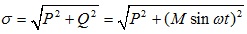
| M | = The amplitude of the impact load |
| P | = The axial force, KN |
| Q | = The impact load, KN |
| Rn | = Interface strength in the normal direction, MPa |
| Rt | = Interface strength in the tangential direction, MPa |
| T | = Rotary cutting force, KN |
| h | = The intrusion depth, mm |
| h | = The intrusion depth of the tooth, mm |
| kn | = The contact stiffness in the normal direction, Pa/mm |
| kt | = The contact stiffness in the tangential direction, Pa/mm |
| l | = The certain length parameter, mm |
| r0 | = The radius of the induced hole, mm |
| r1 | = The radius of the cone bit, mm |
| t | = Time, s |
| vr | = The drilling rate of the cone bit, mm/s |
| σ' | = The normal stress on the failure surface, MPa |
| τ' | = The shear stress on the failure surface, MPa |
| θ | = The tooth blade angle,° |
| βc | = The critical angle of closed,° |
| βs | = The critical angle of sliding,° |
| βrs | = The critical angle of the reverse sliding |
| φ | = The angle between failure surface and horizontal plane,° |
| ω | = The angular speed of the impact load, rad/s |
| σ | = The resultant force of the axial force and the impact load, KN |
| β | = The angle between the elliptical crack’s half-length and the resultant force, ° |
| µ | = Coulomb friction coefficient |
| γ | = The crack density |
| σ̂ | = The normalized stress |
| ϕ | = The internal friction angle,° |