RESEARCH ARTICLE
Analysis on the Operation Fatigue of Deepwater Drilling Riser System
Xiuquan Liu*, Guoming Chen, Jingjie Fu, Jingqi Ji, Qiang Song, Yuanjiang Chang
Article Information

Identifiers and Pagination:
Year: 2016Volume: 9
First Page: 279
Last Page: 287
Publisher Id: TOPEJ-9-279
DOI: 10.2174/1874834101609010279
Article History:
Received Date: 27/02/2016Revision Received Date: 26/09/2016
Acceptance Date: 10/11/2016
Electronic publication date: 14/12/2016
Collection year: 2016
open-access license: This is an open access article licensed under the terms of the Creative Commons Attribution-Non-Commercial 4.0 International Public License (CC BY-NC 4.0) (https://creativecommons.org/licenses/by-nc/4.0/legalcode), which permits unrestricted, non-commercial use, distribution and reproduction in any medium, provided the work is properly cited.
Abstract
Fatigue is one of main failure modes of deepwater drilling riser system. Analysis models of wave induced fatigue and vortex induced fatigue of deepwater drilling riser are established according to the riser connection, installation and hang-off operations. Characteristics of wave induced fatigue and vortex induced fatigue of riser system in different operation modes are studied. The influence of each operation fatigue on the combined fatigue is also identified. The results show that wave induced fatigue damage and vortex induced fatigue damage of upper riser are large in installation and hard hang-off modes. The fatigue damage of riser system in soft hang-off mode is less than that in hard hang-off mode. The combined fatigue damage of the upper and lower riser is large. The lower riser is under the influence of wave induced fatigue and vortex induced fatigue, while the upper riser is mainly under the influence of wave induced fatigue, especially that in installation and hang-off modes. The fatigue damages of riser in installation and hang-off modes have a great influence on the combined fatigue of riser and cannot be neglected in riser fatigue analysis.
1. INTRODUCTION
Deepwater drilling riser is a major component of offshore drilling system that connects drilling platform with subsea wellhead. The primary functions of deepwater drilling risers are to provide fluid passage between subsea wellhead and drilling platform, to support auxiliary lines, to guide drilling tools into wells, and to serve as a running and retrieving string for the blowout preventer (BOP) stack. As a flexible structure, deepwater drilling riser is vulnerable to dynamic loads and fatigue is one of its main failure modes due to the long-term oscillatory environmental loads. The riser fatigue can be divided into wave induced fatigue and vortex induced fatigue. The wave induced fatigue is mainly caused by ocean waves and the movements of drilling platform including high frequency response to the waves and low frequency excursion. The vortex induced fatigue is mainly caused by vortex release of ocean current when it flows around the drilling riser [1, 2].
Much research on the fatigue assessment of deepwater drilling riser system has been carried out at present. Time-domain method and frequency-domain method are often used to calculate wave induced fatigue. In the time-domain method, the dynamic response and fatigue of riser system are calculated directly and the calculation accuracy is high. Compared with time-domain method, frequency-domain method is low in calculation accuracy due to its linearization of dynamic analysis equations [3-6]. The analysis methods of vortex induced vibration (VIV) include experiment, CFD simulation and empirical model. The first two methods are mainly applied on the mechanism research of VIV of riser, while the empirical model has a good application in the vortex induced fatigue analysis of riser [7-11]. The above studies are focused on the fatigue assessment of riser in connection mode. In fact, the operation modes of deep water drilling riser are various, including installation, connection, hard hang-off and soft hang-off. The riser fatigues in various operation modes have not been studied. Besides, the combined fatigue and the occupancy of each operation fatigue should also be studied based on the calculated fatigues of riser in different operation modes.
In this paper, different operation modes of deep water drilling riser system are introduced. The analysis method of operation fatigue of riser is established. Characteristics of vortex induced fatigue and wave induced fatigue of riser system in different operation modes are studied. The combined fatigue and the occupancy of each fatigue are also calculated. The results can provide a reference for operation fatigue design, analysis and management of deep water drilling riser system.
2. ANALYSIS MODEL
2.1. Operation Modes
Four typical operation modes of deepwater drilling riser are connection, installation, hard hang-off and soft hang-off, as shown in Fig. (1). Deepwater drilling riser system and BOP are installed before deep water drilling and recovered to platform after deep water drilling and completion. In installation mode, the top of riser is hanged on chuck and the bottom of riser is connected to BOP, as shown in Fig. (1a). In connection mode, the top of riser system is connected to drilling platform via tensioner system and upper flex joint (UFJ), and the bottom of riser system is connected to BOP, subsea wellhead and conductor system through lower flex joint (LFJ) and lower marine riser package (LMRP). In harsh environment, the connector between LMRP and BOP should be unlocked, and riser is hanged on drilling platform either in hard hang-off mode or soft hang-off mode. The top of riser is directly connected to chuck in hard hang-off mode, while the riser is hanged on the platform through tensioner system in soft hang-off mode [12, 13].
 |
Fig. (1). Typical operation modes of riser. |
2.2. Vibration Analysis Model
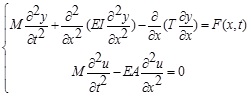
In wave induced fatigue mode, the drilling riser system is subjected to dynamic loads from wave and platform motion. Wave load and horizontal motion of platform excite the transverse vibration of riser system, while heave motion of platform excites the longitudinal vibration of riser system. The relevant horizontal and longitudinal dynamic analysis equations of riser system can be expressed as [14, 15]:
 |
(1) |
where M is the mass of per unit length of riser, T is the effective axial tension of riser, F is the load acting on per unit length of riser, u is the vertical displacement of riser, E is the elastic modulus of riser material, I is the inertia moment of riser and A is the sectional area of riser.
The hydrodynamic wave load on the riser can be expressed as:
 |
(2) |
where ρ is the sea water density, Do is the outside diameter of riser, CM is the inertia coefficient, CD is the drag coefficient, uw is the water particle velocity, uw is the water particle acceleration, uc is the steady current velocity, ẏ is the riser velocity and ӱ is the riser acceleration.
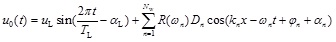
The top end of drilling riser system is connected to the drilling platform in all the four operation modes. The top boundary of drilling riser system is mainly determined by platform motion. The drilling platform motion under random wave loads can be expressed as [16]:
 |
(3) |
where uL is the single amplitude of platform drift motion in the horizontal direction, TL is the period of platform drift motion, αL is the phase difference between the drift motion and wave (usually taken as zero), R is the response amplitude operator, Dn is the amplitude of the n-th wave; kn is the number of the n-th wave; ωn is the circular frequency of the n-th wave; φn is the initial phase of the n-th wave; αn is the phase difference between wave motion and wave frequency motion (usually taken as zero).
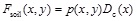
The bottom boundary of drilling riser system depends on the operation mode. In installation and hang-off modes, the bottom of drilling riser system is unconstrained. While in connection mode, the drilling riser system is connected to conductor which is restrained by surrounding soil. The soil resistance force per unit length on the conductor under the mudline is expressed as:
 |
(4) |
where p is the resistance pressure; Dc is the outside diameter of conductor.
Time-domain finite element method is often applied to solve wave induced vibration equations. Finite element analysis model of riser system is built using ABAQUS software. The riser system is divided into a number of elements. The riser system is modeled by pipe element. The flex joint is modeled by joint element with rotation stiffness. The soil resistance force on the conductor is modeled by nonlinear spring element. The platform motion is applied as top boundary condition of riser system. Then, the finite element model can be solved by ABAQUS marine engineering module ABAQUS/Aqua.
In vortex induced fatigue mode, a force perpendicular to the ocean current direction is exerted on the riser because of the periodic shedding of the vortices. The riser’s response to the ocean current may be multi-mode or single-mode dominated. However, the VIV of riser system is complicated and hard to analysis directly. SHEAR7 is chosen for VIV analysis of riser because of its good application in the vortex induced fatigue analysis of riser.
2.3. Fatigue Analysis Model
The dynamic stress of riser system is calculated based on proposed wave induced vibration analysis model. Rainflow cycle counting method is used to extract the stress ranges from the stress time history. A rainflow counting program is developed in PYTHON language which is the embedded scripting language of ABAQUS. The developed rainflow counting program can call the object database of ABAQUS and extract dynamic stress of riser system directly. Then riser fatigue damage is calculated by Eq. (5) according to S-N curve.
 |
(5) |
where m and Cf are parameters of S-N curve; nc is the number of rainflow cycles.
Besides, the vortex induced fatigue of riser system can be calculated directly based on SHEAR7. According to the Miner rule and DNV recommended practice, the combined fatigue damage of riser system is the sum of all kinds of fatigue damage [17]. The combined wave induced fatigue and vortex induce fatigue can be expressed as:
 |
(6) |
 |
(7) |
where DW,ins, DW,con and DW,hang are wave induced fatigue damage in installation, connection and hang-off modes, respectively; DV,ins, DV,con and DV,hang are vortex induced fatigue damage in installation, connection and hang-off modes, respectively; Tins, Tcon and Thang are the time of installation, connection and hang-off operation, respectively.
3. RESUTLS AND DISCUSSIONS
3.1. Basic Parameters
A drilling riser system in 1342 m water depth is chosen for case study. The basic parameters are listed in Table 1. The joint distribution of significant wave height and zero up-crossing period of wave are listed in Table 2. The current profile is shown in Fig. (2). The response amplitude operator (RAO) of drilling platform is shown in Fig. (3). The single amplitude of platform drift motion is 13.42m (1% water depth). The period of platform drift motion is 250 s. The fatigue S-N curve of riser is DNV E curve with cathodic protection (m = 3, Cf = 4.1 × 10¹¹).
| Parameter | Value | Parameter | Value |
|---|---|---|---|
| Top tension of riser (MN) | 3 | Weight of LMRP (kN) | 700 |
| Riser length (m) | 1326 | Height of BOP (m) | 9 |
| Outside diameter of riser (m) | 0.5334 | Weight of BOP (kN) | 2000 |
| Wall thickness of riser (m) | 0.022225 | Wellhead sludge height (m) | 3 |
| Rotation stiffness of UFJ (kN·m/º) | 12.9 | Length of conductor (m) | 83 |
| Rotation stiffness of LFJ (kN·m/º) | 92 | Outside diameter of conductor (m) | 0.9144 |
| Height of LMRP (m) | 4 | Wall thickness of conductor (m) | 0.0381 |
| Wave height (m) | Wave period (s) | |||||
|---|---|---|---|---|---|---|
| <=3 | 3~4 | 4~5 | 5~6 | 6~7 | 7~8 | |
| 0~0.5 | 2.76 | 5.50 | 3.00 | 0.63 | 0 | 0 |
| 0.5~1.0 | 1.23 | 7.44 | 4.04 | 2.78 | 0.82 | 0 |
| 1.0~1.5 | 0 | 8.87 | 5.54 | 2.73 | 1.43 | 0.11 |
| 1.5~2.0 | 0 | 0.95 | 13.20 | 2.41 | 1.09 | 0.20 |
| 2.0~2.5 | 0 | 0.42 | 10.39 | 2.82 | 1.03 | 0.12 |
| 2.5~3.0 | 0 | 0 | 1.15 | 8.67 | 0.52 | 0.16 |
| 3.0~3.5 | 0 | 0 | 0.3 | 5.31 | 0.54 | 0.17 |
| 3.5~4.0 | 0 | 0 | 0 | 2.21 | 1.21 | 0.25 |
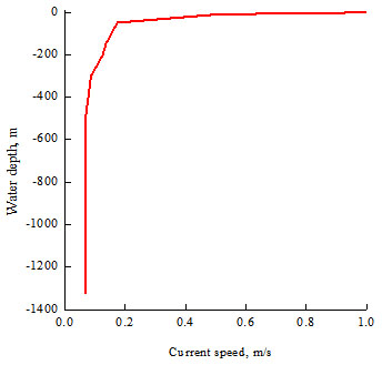 |
Fig. (2). Current profile. |
 |
Fig. (3). RAO of drilling platform. |
3.2. Wave Induced Fatigue
According to the deep water drilling practice, the sea states of riser system in different operation modes are various. In connection mode, the long-term joint distribution of significant wave height and zero up-crossing period of wave are selected for fatigue analysis. In installation mode, sea state in one year return period is chosen for analysis. The relevant wave height is 6 m, and the wave period is 9.5 s. In hang-off mode, sea state in ten years return period is chosen for analysis. The relevant wave height is 11.1 m, and the wave period is 11.6 s. Based on the selected calculation parameters, JONSWAP spectrum is used to simulate the random waves and the motion of drilling platform. Then the wave induced vibration and fatigue damage of riser system in different operation modes are calculated respectively, as shown in Fig. (4).
Fig. (4) shows that in connection mode, wave induced fatigue damage of upper and lower riser is large under the combined influence of wave load and platform motion. The upper riser fatigue damage is primarily affected by the wave load, while the lower riser fatigue damage is mainly affected by the drilling platform motion, especially the drift motion of platform. The single amplitude of platform drift motion can cause a great stress variation of riser near bottom. So the fatigue damage near the bottom end of riser is large. In installation and hang-off mode, the riser system vibrates axially under the influence of the heave motion of platform. The inertia force generated by riser axial vibration can increase axial load of upper riser greatly, and the upper riser experiences great fatigue stress. So the wave induced fatigue damage of the upper riser is larger than that of the lower riser. Compared with riser fatigue damage in hard hang-off mode, the riser fatigue damage in installation and soft hang-off mode is smaller. In installation mode, the riser installation condition is mitigatory and the riser axial vibration is light. The relevant fatigue stress and damage are small. In soft hang-off mode, the riser is hanged on the platform via tensioner system which can relieve axial vibration of riser effectively. So the riser fatigue damage is smaller than that in hard hang-off mode.
 |
Fig. (4). Wave induced fatigue. |
3.3. Vortex Induced Fatigue
In connection mode, the operation condition of riser is normal sea state and the long-term current profile is simulated based on the Weibull distribution model. In installation mode, sea state in one year return period is chosen for analysis and the relevant surface current velocity is 1.07m/s. In hang-off mode, sea state in ten years return period is chosen for analysis and the relevant surface current velocity is 1.43 m/s. Based on the above parameters, vortex induced fatigue of riser in different operation modes is analyzed respectively, as shown in Fig. (5).
Fig. (5) shows that the vortex induced fatigue of riser system in different operation modes is different from each other obviously. In connection mode, the effective tension of riser system decreases with the increase of water depth and the modal curvature of lower riser system is larger than that of upper riser. So the vortex induced fatigue damage of lower riser is large. In installation and hard hang-off modes, the upper riser is connected to the drilling platform directly which can cause large fatigue stress during VIV. So the vortex induced fatigue damage is large in upper riser while small in other positions. In soft hang-off mode, the flex joint between the upper riser system and platform can decrease the vortex induced fatigue damage of riser system effectively. The maximum vortex induced fatigue damage appears at the middle-lower part of riser system which is less than that in hard hang-off mode. Therefore, soft hang-off can improve the vortex induced fatigue property of riser system effectively.
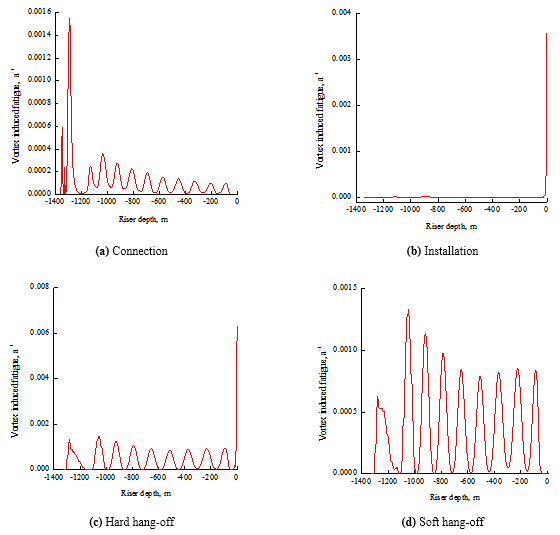 |
Fig. (5). Vortex induced fatigue. |
3.4. Combined Fatigue
Generally, the average period of well drilling and completion is 60 days, of which riser installation and retrieving time is 3 days, the mean time of typhoon-avoidance evacuation is 1 day and the remaining time is connection time. Assume that the riser is in soft hang-off mode in typhoon condition due to its good fatigue performance. Based on the above operation parameters, the combined fatigue damage of riser system is calculated and the occupancy of each fatigue in a drilling period is also determined, as shown in Figs. (6 and 7), respectively.
Figs. (6 and 7) show that the combined fatigue damage of upper and lower riser is large. Two fatigue damage peaks appear at the lower riser due to the combined effect of wave induced fatigue and vortex induced fatigue. Peak 1 is primarily affected by the wave induced fatigue damage in connection mode, and peak 2 is mainly affected by vortex induced fatigue damage in connection mode. The maximum fatigue damage appears at the upper riser system and is mainly affected by wave induced fatigue, especially that in installation and hang-off modes. Although riser installation and hang-off time is short, the fatigue damage during this time has a great influence on the combined fatigue of riser and cannot be neglected.
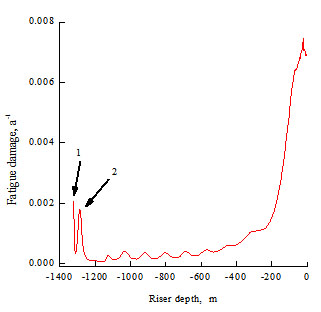 |
Fig. (6). Combined fatigue damage. |
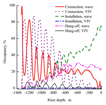 |
Fig. (7). Occupancy of each fatigue. |
CONCLUSION
1. In installation and hard hang-off modes, the upper riser is connected to drilling platform directly. The platform motion and the inertia force generated by riser axial vibration can increase axial load of upper riser greatly during wave induced vibration. The modal curvature and stress are also great during VIV. So the fatigue damage is large in upper riser while small in other parts.
2. Compared with riser in hard hang-off mode, the riser is hanged on the platform via tensioner and flex joint in soft hang-off mode which can relieve the influence of wave induced vibration and VIV on riser system effectively. The riser fatigue damage is smaller than that in hard hang-off mode. The soft hang-off can improve fatigue property of riser system effectively.
3. The upper and lower riser parts are hot spots of operation fatigue damage. The lower riser is primarily affected by wave induced fatigue and vortex induced fatigue in connection mode and the upper riser is mainly affected by wave induced fatigue, especially that in installation and hang-off modes. Although riser installation and hang-off time is short, the fatigue damage during this time is large and cannot be neglected.
CONFLICT OF INTEREST
The authors confirm that this article content has no conflict of interest.
ACKNOWLEDGEMENTS
The authors wish to acknowledge the financial support of the National Program on Key Basic Research Project (2015CB251203), Program for Changjiang Scholars and Innovative Research Team in University (IRT14R58), and Natural Science Foundation of Shandong Province (ZR2014EL018).