RESEARCH ARTICLE
A Review of Numerical Simulation Strategies for Hydraulic Fracturing, Natural Fracture Reactivation and Induced Microseismicity Prediction
A.S.A. Shahid1, P.A. Fokker2, V. Rocca1, *
Article Information
Identifiers and Pagination:
Year: 2016Volume: 9
Issue: Suppl-1, M5
First Page: 72
Last Page: 91
Publisher Id: TOPEJ-9-72
DOI: 10.2174/1874834101609010072
Article History:
Received Date: 24/4/2015Revision Received Date: 30/7/2015
Acceptance Date: 12/08/2015
Electronic publication date: 30/06/2016
Collection year: 2016
open-access license: This is an open access article licensed under the terms of the Creative Commons Attribution-Non-Commercial 4.0 International Public License (CC BY-NC 4.0) (https://creativecommons.org/licenses/by-nc/4.0/legalcode), which permits unrestricted, non-commercial use, distribution and reproduction in any medium, provided the work is properly cited.
Abstract
Hydraulic fracturing, natural fracture reactivation and resulting induced microseismicity are interconnected phenomena involved in shale gas exploitation. Due to their multi-physics and their complexity, deep understanding of these phenomena as well as their mutual interaction require the adoption of coupled mechanical and fluid flow approaches. Modeling these systems is a challenging procedure as the involved processes take place on different scales of space and also require adequate multidisciplinary knowledge. An extensive literature review is presented here to provide knowledge on the modeling approaches adopted for these coupled problems. The review is intended as a guide to select effective modeling approaches for problems of different complexity.
1. INTRODUCTION
Shale gas reserves have become more and more important for the US energy mix and thus they have had a global impact. As it is well known, the very poor hydraulic properties of shales make the exploitation of these reservoirs uneconomical if produced conventionally. Only the activation of their natural fracture network and/or the opening of new fractures makes them economic [1]: if properly stimulated/generated via hydraulic fracture treatments, fractures become preferential flow channels for gas exploitation.
Hydraulic fracturing is a complex multi-physics phenomenon where fluid flow in the formation is fully coupled with the geomechanics of the reservoir rock. The efficiency of fracturing operations is strongly affected by the interaction with pre-existing natural fractures, which leads to more complex fracture geometries.
The mechanical and petrophysical (i.e. permeability) changes due to hydraulic fracturing occur deep in the subsurface and direct observation of all the processes is impossible. The only direct measurements of subsurface reservoirs come from the cores and the well logs, which provide very limited information about the reservoir. Well-testing and microseismic mapping may give good spatial information but these methods are indirect and contain lots of uncertainties due to a number of simplifying assumptions in the interpretation process. This incomplete set of information generates a need to develop an alternative workflow to obtain understanding of the physics involved and ultimately to optimize the hydraulic fracturing process. Various modeling approaches are used to study the system behavior using the limited information available.
Developing a representative model to simulate hydraulic fracturing is a challenging task as the coupled-physics processes involved take place on different spatial and temporal scales. An adequate model should give a realistic representation of the processes involved while keeping the computational cost within appropriate limits. Modeling approaches available in the industry range from simple standalone elasto-plastic correlations to complex multi-scale fluid-structure interaction (FSI) simulators.
The authors have not found a comprehensive review of existing techniques, strategies, advances, problems and ongoing research in numerical modeling for hydraulic fracturing and related phenomena like fracture reactivation and microseismicity for unconventional hydrocarbon resources. The present review has been compiled to fill that gap. In addition, it also deals with other geotechnical domains where hydraulic fracturing or fracture reactivation is used (like geothermal energy applications) if there can be a knowledge transfer with the domain of unconventional hydrocarbon resources. Indeed, if the relevant governing equations are the same and the boundary conditions are the same, the solutions provided for geotechnical applications will be valid for hydraulic fracturing as well.
As in any modeling effort, the quality of the input parameters is critical for the reliability of the model output. However, the procedures for determining these parameters are not discussed here. A large number of experimental and analytical studies are available that address the measurement of the required physical properties of the reservoir rock being modeled. In summary: indirect methods at well-scale and lab analysis at core scale. While the indirect methods usually lack in accuracy, they are able to address system heterogeneity. On the other hand, laboratory-scale experimental data can usually evaluate parameter values with a higher level of accuracy, but they must be subsequently extended at model scale. Moreover, compared to the intact rocks, fractures/faults samples are always disturbed and less representative of the real in situ conditions.
The paper starts with a brief overview of coupled geomechanical and fluid flow modeling schemes, followed by a basic geomechanical description of hydraulic fracturing and natural fracture behavior, as well as their applications. Then, different modeling workflows and simulation approaches for the phenomena under analysis are summarized and critically compared. This review is followed by a discussion of case-studies addressing simulations of interaction between natural fractures and hydraulic fractures. Finally, a concise survey on modeling setups developed to predict microseismicity in reservoirs undergoing fracturing or fracture reactivation is presented. The paper closes with observations about the suitability of the different schemes for different applications and under various circumstances.
2. BASICS ON HYDRAULIC FRACTURING, NATURAL FRACTURE REACTIVATION AND INDUCED SEISMICITY
The sweep efficiency of shale reservoirs is strongly affected by the extent and the continuity of the fracture networks induced via hydraulic fracture treatments. The presence of natural fractures leads to the development of complex fracture geometry, also with favorable effects on hydrocarbon production.
Natural fractures and faults can be viewed as a weakness plane in the rock which, on the one hand, reduces the mechanical strength of the overall rock mass and, on the other hand, alters the fluid flow characteristics. They are originated from different geological events such as regional and tectonic stresses, regional burial and local effects of major faults and folds. Over time, these discontinuities are sealed with minerals and locked due to, for example, frictional forces between the two fracture walls or fine migration, making them nearly impermeable to flow. If properly stimulated via hydraulic fracture treatments, natural fractures become preferential flow channels for gas exploitation. Furthermore, tensile failure induced by hydraulic fracturing stimulations can also lead to fracture propagation into intact rock and/or reactivation of existing fractures.
Hydraulic fracturing operations induce a stress state into the formation which exceeds the mechanical strength of the system: the induced failure can evolve both in tensile or in compressional mode with associated tensile or shear fracture generation, respectively. Fig. (1) shows the three possible fracture propagation modes.
When fluid pressure induces a tensile stress into intact rock that exceeds the minimum principal stress value, opening/tensile fractures start propagating perpendicular to the least principal stress direction (Mode I, Fig. 1a). The fluid pressure, the mechanical strength of the rock and the in situ stress state control the length and the direction of tensile fracture evolution. In normal faulting and strike-slip faulting regimes, these fractures are vertical because the minimum in-situ stress is oriented in horizontal direction. Furthermore, horizontal fractures are usually observed in shallow regions where the overburden weight is not predominant. In reverse faulting stress regimes or in shallow rock formations where the minimum in-situ stress can be in the vertical direction, a tensile fracture can be horizontal.
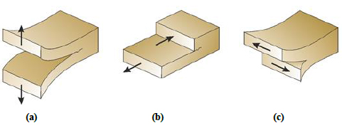 |
Fig. (1). Fracture Modes I (a) (left), II (b) (center) and III (c) (right) [2]. |
In a fracture/fault system, the presence of discontinuities or weakness planes affect the way the induced hydraulic fractures propagate. They can force the hydraulic fractures to deviate from the general propagation direction (direction of least resistance in case of tensile failure) and lead to extensive branching [3, 4], or they can arrest the hydraulic fracture at the point of interaction. Extensive technical literature [5-9] experimental studies and simulation analysis is available on the effects of pre-existing fractures on hydraulic fracturing evolution.
A microseismic event is a micro-earthquake resulting from hydraulic fracturing treatment when rock breaks and releases the energy in form of elastic waves that can propagate through the subsurface. Microseismic events can be generated whenever the rock breaks, as a result of induced fracturing or in case of reactivation of existing fractures. The induced microseismicity during hydraulic fracturing is mainly the result of shear failure (mode II) on existing natural fractures or induced hydraulic fractures.
Failure mechanisms of existing fractures are commonly represented by specific failure criteria conveniently selected according to the investigated scenarios [10]. If the shear stresses induced by the difference between principal stresses satisfy the failure criterion, natural fractures can be reactivated and slip along the fracture plane (Mode II, Fig. 1b). The onset of shear or sliding fracturing is controlled by the effective stresses and the failure criterion; the dynamics of the rupture process are controlled by the frictional behavior of the fault and the elasticity of the intact rock walls. The failure characteristics depend on fracture plane roughness and asperities that interlock the fracture planes making it difficult to slide against each other. Normal stress on the fracture planes press these planes against each other keeping them stable while the shear stress tends to shear the fracture. Once the acting stress increases to a level where it overcomes the resistance to sliding, the fracture reactivates. [11].
Mode III fractures (also called tear fractures) (Fig. 1c) also initiate because of an excess in shear stress and they propagate perpendicular to the maximum principle direction [12].
3. MODELING APPROACHES
Mechanical analysis can be developed at different scales and levels of integration with the other disciplines. Traditionally, rock mechanics has been included in conventional reservoir simulations by the adoption of a constant, or at most, pressure-dependent rock compressibility parameter [13]. In reality the effects of rock mechanics on fluid flow phenomena and vice versa can be much more complex: for example, the behavior of unconsolidated porous media, of critically stressed faults and of highly stress-sensitive rocks is strongly affected by the coupling effects. Furthermore, the rock mechanics and fluid flow coupling represents a principal factor for the phenomena involved in fault reactivation processes with associated transmissivity changes and induced seismicity, in high-pressure injection operations and in hydraulic fracturing activities. A deep insight of these systems/phenomena requires appropriately addressing the dependencies between fluid flow and stress-strain processes.
The key concept of coupled processes is based on Terzaghi’s principle: a change in fluid pressure will change the effective stresses and cause the reservoir and the surrounding rocks to deform; conversely, the pressure field itself is also a function of the deformations and, hence, the coupling [14].
Stress effects the total pore space (and porosity, as well) with a consequent modification in pressure. Furthermore, porosity change results in a permeability variation, which again affects fluid flow behavior [15].
The degree of interaction between mechanics and fluid flow aspects is also a function of the loading condition and of the system deformation/strength characteristics. Consequently, the adopted simulation technique must be adequate to the complexity of the phenomena under analysis. In case of linearly elastic deformation behavior, for example, mechanical effects can be included in the reservoir simulation using appropriate position-dependent relationships to approximate pressure-dependent permeability and/or porosity changes. Hettema et al. [16] showed the importance of the stress path, which is defined as the change of stress induced by the change in pressure, and which can vary depending on the position in and around the reservoir. Settari et al. [17] presented different approaches to transfer stress-dependent parameters to pressure-dependent functions, which then can be used in conventional standalone reservoir simulators. A different situation evolves when linear elasticity does not apply anymore. For instance, if rock failure is reached due to mechanical loading, the changes in porosity and permeability will be much more pronounced and irreversible (plastic) and they cannot be properly addressed through linear relationships with pressure. In addition, while the change in porosity under elastic behavior is a linear relationship, models to describe those changes under plastic deformation are still a matter of debate. Mostly in these cases, the use of geomechanical modeling to better define the complete reservoir behavior is essential to fully define all the processes.
The technical literature shows several approaches to model formation behavior with different degrees of coupling between rock deformation and fluid flow. Most of the coupled modeling studies, published in the literature, deal with conventional reservoirs under compaction, wells reaching failure, seal-integrity and mechanical problems associated with injection and production. The following sections provide a brief overview of the techniques employed and the tools available currently.
3.1. Coupling Techniques
Different strategies were developed and successfully applied to solve coupled hydro-mechanical problems: fully-coupled, iteratively-coupling and one-way coupling.
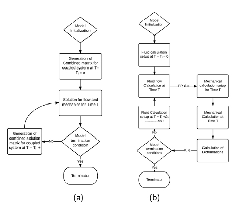 |
Fig. (2). Flow-chart for fully-coupled (a) and Iteratively-coupled (b) schemes. |
The fully-coupled scheme, also called implicit coupling, performs multiphase flow and stress-strain calculation simultaneously solving one system of equations within a single numerical approach and the same spatial and temporal discretization. This approach has the advantage of internal consistency; it is also the most stable technique and preserves second order convergence of nonlinear iterations. On the other hand, the fully-coupled scheme is the most demanding concerning computational time and numerical implementation.
Fig. (2a) shows the general flow-charts adopted in the fully-coupled scheme.
In the iteratively coupled approach, the basic equations for multiphase porous flow and rock deformation are solved separately and sequentially, and the calculation of coupling terms is iterated at each time step or after a preselected number of time-steps (Fig. 2b). The exchange of information between the reservoir simulator (generally developed according to the finite difference discretization method – FDM) and the geomechanics module (generally developed according to the finite element discretization method – FEM) is commonly handled through a transfer and conversion code, which also checks the convergence of the coupling iterations. The adopted convergence criterion is typically based on pressure or stress changes between the last two solution iterations [18]. The adopted coupling variables are usually related to the key reservoir characteristics in order to highlight the most important coupling phenomena, such as volume changes, stress-dependent permeability, saturation-dependent rock strength, etc.
The models developed by Rodrigues et al. [19] and Rustquist [20] are two examples of the modular philosophy where dedicated reservoir codes (such as IMEX by CMG® or TOUGH by Lawrence Berkeley National Laboratory) and dedicated geomechanics codes (such as FLAC/FLAC3D by Itasca®) are adopted to achieve the iteratively coupled scheme (Fig. 3).
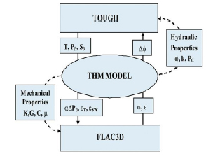 |
Fig. (3). Coupled modeling scheme, [20]. |
Dean et al. [21] and Jalali et al. [22] compared the fully and iteratively coupled techniques through a series of sensitivity analyses performed on simple case studies. Dean et al. [21] also analyzed different convergence criterions for the different coupling schemes and concluded that, if sufficiently tight convergence tolerances were adopted, the fully coupled approach and the iteratively coupled one provided the same results. If the correct convergence criterion is applied, an iteratively coupled method ensures loss of accuracy.
Finally, the one-way coupling approach allows the determination of the formation stress/strain change based on the pore pressure evolution calculated by the reservoir simulator. Yet the pressure field is supposed to be independent from the induced rock deformations: no strain-dependent variation of petrophysical parameters is incorporated into the reservoir simulator.
The higher the degree of coupling, the higher the need for computing time, technical skills and quality/quantity of input data, thus it is important to evaluate which degree of coupling is needed for each specific case, considering that different reservoir conditions and operational scenarios involve different levels of interaction between rock deformation and fluid flow. Alternative solutions may be taken into consideration such as the possibility to adopt sub-modeling techniques.
4. MODELING HYDRAULIC FRACTURING
There are a number of good overviews and general studies available on hydraulic fracturing [23-28]. The present paragraph briefly summarizes the most widespread theoretical models and the adopted numerical approaches.
4.1. Classical 2D, P3D and PL3D Models
Most modeling of hydraulic fracturing is based on the work of Sneddon [29] and Sneddon and Elliott [30] on crack opening, both for plane strain (2D) and for circular, penny-shaped cracks. Further evolutions and improvement of their theory were elaborated [31] until the formulation of the well-known PKN model [32]. The PKN model includes fluid loss effects and assumes an elliptical flow channel of which the width is determined by the frictional pressure drop. It is therefore appropriate for contained fractures with a large length / height ratio.
In 1955, Khristianovic and Zheltov [33] separately developed their hydraulic fracturing model, which was improved by Geertsma and de Klerk [34] into the KGD plane strain model. These models treat hydraulic stimulation as one single planar fracture that propagates starting from the wellbore away into the formation. The plane-strain approach makes the model applicable for cases where the length / height ratio is small and the fracture is initiated from a line source of perforations in the well.
Fig. (4) schematizes the fracture geometry of PKN, KGD and Sneddon’s models.
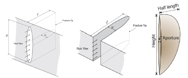 |
Fig. (4). Schematics of fracture geometry defined by PKN (left), KGD (middle) and Penny-shaped (right) [35]. |
Two types of 3D models were developed from these simple theoretical models: the pseudo-three-dimensional (P3D) and the planar-three-dimensional (PL3D) models. These extensions to the analytical models allowed to simulate hydraulic fracture propagation in multilayered reservoir rock system and were not restricted by fracture height [36].
P3D models are widely used in the industry for hydraulic fracture design to idealize fracture propagation in multi-layered formations. P3D models modify the PKN (2D) model by considering fracture height in combination with fracture length and width. The added height variation of the fracture can be linear or parabolic [36].
In the PL3D modeling approach a plane is discretized at which fracture propagation can occur within a layered system. The final geometry of the induced fracture can thus be irregular, depending on the mechanical parameters of each layer. Fluid flow in the fracture is coupled with the reservoir rock elasticity and fracture propagation is controlled by the tensile strength of the rock. Fig. (5) shows the model of an induced hydraulic fracture in a multilayered reservoir using TerraFracTM, 2D finite element software based on the PL3D hydraulic fracturing approach.
P3D models can suffer numerical instability in case of systems with non-monotonically varying confining stresses in a layered system and also when there is unconfined height growth of fractures. PL3D models can handle these situations better [35].
To address the complex modeling requirements for hydraulic fracturing in unconventional reservoirs different numerical approaches and model discretizations have been employed. Depending on the modeling approach adopted by different authors these models can be divided into groups. The following subsections will discuss this.
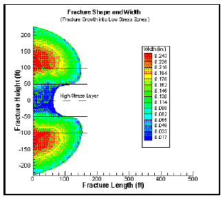 |
Fig. (5). Schematics of fracture geometry defined by PKN (left), KGD (middle) and Penny-shaped (right) [37]. |
4.1.1. Finite Element Method
In the finite element model (FEM) a reservoir system is discretized in subdomains (finite elements) of coded shape (typically tetrahedrons) using a mesh. On each element the solution is described by a linear combination of simple shape functions, usually polynomial, that locally approximate the global solution. One of the advantages of using FEM to simulate fracture propagation is that it allows to consider fractures that have complex 3D shapes that transcend the limitations of 1D or 2D models that have been used in the field for decades. Complex geometries with heterogeneous and anisotropic properties can be addressed. The fluid flow and geomechanical deformations are coupled based on Biot’s poro-elastic theory [38, 39] and fracture propagation is modeled using linear elastic fracture mechanics (LEFM). Technical literature shows a number of applications of the FEM method to study the restriction of hydraulic fracture propagation by natural fractures and discontinuities [40, 41]. Fig. (6) shows hydraulic fracture initialization and propagation resulted from utilizing a finite element modeling approach.
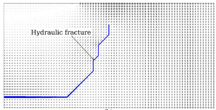 |
Fig. (6). FEM hydraulic fracture model [41]. |
Modeling fracture growth in FEM framework requires re-meshing of the reservoir grid that is intersected by a propagating hydraulic fracture. This re-meshing coupled with data translation, when two different numerical codes are involved (FEM for geomechanics simulation and FVM-Finite Volume Method and/or FDM-Finite Different Method for fluid-flow simulation), makes these FEM models computationally very expensive, especially in the case of complex fracture network geometries. To deal with this problem, the Extended Finite Element method (XFEM) was developed where induced fractures propagate without the need of re-meshing of the grid, under the assumption of small deformation [42]. This is achieved by introducing discontinuous element solutions into elements crossed by the fracture. The XFEM approach reduces the computational cost and can potentially become an effective technique to model hydraulic fracturing. The validation of such a complex approach is currently not entirely addressed, specifically in case of complex fracture geometries [43-45], but a good degree of confident has been built over the past years.
4.1.2. Boundary Element Method
The Boundary Element Method (BEM) is suitable as a hydraulic fracture-modeling tool: it approximates the elastic solution in the solid material using a discretization of the boundaries of the domain only – i.e. only the fracture planes. In addition, there is no need for an artificial boundary far away when modeling infinitely extending systems, which are common in geomechanical problems. In the BEM, the domain is divided into two regions: the interior (the fracture) and the exterior (the intact rock), separated by the boundary (the fracture wall), which is discretized in elements. Every element generates a stress and strain field in the complete domain, which satisfies the appropriate equations. Fig. (7) presents an example of discretized fracture according to the BEM in a 2D domain.
The advantage of the BEM is that it eliminates the need to discretize the model inside the continuum; however, the solution of every boundary element generates a field at every other boundary element, which results in required solutions for dense matrices. As a result, the BEM is inefficient for large systems. Much effort is put into the development of better approximation and iterative algorithms. Further disadvantages of the BEM are that it is not capable of modeling heterogeneity in the rock properties and that the accurate handling of fractures intersecting at low angles is problematic [46].
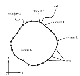 |
Fig. (7). BEM fracture discretization example in 2D [47]. |
The Displacement Discontinuity Method (DDM) is a derivation from the BEM. In the DDM straight elements are distributed with constant displacement jumps along the boundary of the fracture [48]. The DDM has been widely applied [4, 49-51] to assess the effect of different parameters on hydraulic fracture phenomena: stress anisotropy, interfacial friction, thermal stresses, etc.
4.2. Effective Continuum Modeling
The effective continuum modeling approach is used for modeling hydraulic fracturing in unconventional as well as in geothermal reservoirs. In a 2D or 3D discretization of the domain, a number of lines or planes for hydraulic fractures are predefined, on which stress changes due to pore pressure evolution can cause effective continuum properties to vary. Fracture initialization and propagation are modeled as a change in mechanical and petrophysical properties [52].
Several authors [52-55] adopted the continuum modeling approach to model thermal-hydro-mechanical processes.
4.3. Discrete Element Method
The Discrete Element Method (DEM, also called Distinct Element Method) uses an aggregation of mutually interacting discrete elements to simulate a discontinuous system; these bodies can be rigid or deformable. The interactions are calibrated in such a way that the resulting macroscopic behavior mimics the behavior of the chosen solid material. Failure of the material can be modeled by damaging the interaction forces between the elements. Fractures can thus develop in a relatively free manner, in any direction, depending on the applied loading. The change in position of the elements is calculated using Newton’s equations of motion. Cundall and Strack [56] and Cleary [57] used spheres and disks as distinct elements to discretize the material, later Cundall [58], and Cundall and Hart [59] and Walton [60] used polygons for this purpose. Then polyhedral blocks (rigid or deformable) were used as distinct elements in combination with compliant contacts in three-dimensional DEM models by Starfield and Cundall [61] and Hart et al. [62]. Recently Nagel et al. [63] used the DEM to develop a three-dimensional coupled model to simulate hydraulic fracturing in naturally fractured reservoirs.
The main challenges related to the DEM method can be summarized as following:
- Use of very simple geometries for the particles (circles or spheres), which can neglect mechanical effects of roughness or edges.
- Simplified representation of the fluid flow (simplified laminar flow or linear Darcy’s-type relations).
- Limited coupling between fluid flow and mechanics (generally one-way).
- Limitation for complex fracture description (the material is no longer a continuum).
Fig. (8) shows a schematic of the particle-based discrete element method (P-DEM) modeling approach where disks are used as distinct elements.
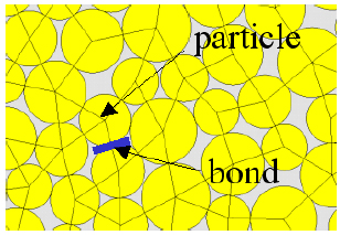 |
Fig. (8). Schematic of P-DEM grid in 2D [64]. |
In the P-DEM, the solid sample being modeled is made up of a number of randomly packed particles (disks in 2D, spheres in 3D). Virtual bonds between adjacent particles (normal and shear) hold them together. Starting from these microscopic forces a macroscopic constitutive relation is derived, and a yield stress for breaking the bonds is employed to produce a macroscopic failure criterion. However, the use of cylinders (the discs in 2D) or of spheres to represent the inner mechanics of rocks is a very relevant limitation of DEM. Eliminating the geometrical complexity of the grains leads to errors at the macroscopic scale.
The P-DEM is well suited for modeling heterogeneous systems by using variable rock mechanical properties and difficulties in discretizing volumes around the fractures are limited. However, the computational cost of the approach poses a limitation to the number of particles that can be used to define a rock sample. With present hardware, laboratory-scale tri-axial rock failure tests can be effectively validated using particle-based DEM models. Furthermore, grid-refinement operations are usually time-expensive and the iterative procedure to find calibrated macroscopic properties of the modeled rock sample often requires extensive trial and error.
The P-DEM method was successfully applied by Min et al. [65] and Deng et al. [66] to model hydraulic fracturing in Enhanced Geothermal System (EGS) applications. Fig. (9) represents an example of Min’s modeling results. It maps the damage levels in the rock sample, representing the time evolution of fracture propagation during mechanical loading. The model qualitatively reproduces the irregular shapes often observed in this type of applications.
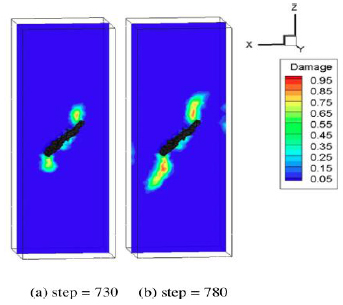 |
Fig. (9). Damage level at two different modeling steps with P-DEM approach [65]. |
5. MODELING NATURAL FRACTURE BEHAVIOR
Natural fractures and faults represent a weakness point in the mechanical behavior of the rock and may act as a more permeable channel than the intact rock. Modeling the coupled dynamic behavior of such discontinuities is challenging because of the complex physics involved. In fact, fault/fracture reactivation depends not only on the in-situ state of stress and pore pressure, but also on the discontinuity orientation and its coefficient of friction. Furthermore, their flow properties (porosity, permeability, transmissibility) are affected by their geometry, lithology, and morphology together with the existing in situ stress state and pore pressure.
Biot’s poroelastic theory [38, 39] represents the base of the coupled hydro-mechanical modeling approaches developed to simulate fractures and fault behavior. The technical literature is rich in research focusing on the analysis and simulation of naturally fractured reservoir behavior during their development. Some authors have tried to model natural fracture interaction with hydraulic fractures during reservoir stimulation jobs as well. The majority of the authors [17, 67-71] agree that in the case of reservoirs with highly deformable sections (fractures) direct coupling between geomechanics and fluid flow is essential to completely simulate system behavior. In fact, the simple pore compressibility relation adopted in standard flow simulators is not enough to fully account for the peculiar geomechanical aspects of this type of reservoirs [70]. For example, the permeability changes of discontinuity can be orders of magnitude greater than changes in matrix permeability, so an adequate analysis of fracture/fault system is required [72].
To model coupled behavior of a fractured reservoir rock during the development and production phase, different authors have used different approaches, according to different discretization schemes.
The indirect or one-way coupling approach has been successfully used for optimization of relative simple fault/fracture reservoir production [73, 74]. Also, technical literature shows some attempts to apply this methodology for modeling and validating natural fracture reactivation in unconventional reservoirs [75].
However, the most commonly used approach to simulate the fracture/fault system response is the iteratively-coupled scheme. The dynamic behavior of the fractured reservoir in the fluid-flow code is usually simulated using a dual-porosity and/or a dual-permeability approach. In the geomechanical code, discontinuities can be treated as weakness planes in a continuum or as discrete fracture networks (DFN), as will be described later on. This simulation scheme has been widely applied to simulate the coupled processes in conventional reservoir studies: the fault reactivation during production was addressed together with stress-sensitive permeability and shear-dependent fault transmissibility update [76]. Furthermore, the effect of coupling through rock deformation and matrix porosity as well as fracture permeability due to tensile deformation was addressed [77].
Different studies dealt with the effect of the geometrical and mechanical nature of the fault on the reliability of simulation results. Cappa,and Rutquist [78], Rutqvist, et al. [79] and Gan and Elsworth [80], developed an iteratively coupled model where planar fractures were defined in a geomechanical grid as weakness planes but they were not set up to account for the mechanical heterogeneous nature of the fracture planes.
The iteratively-coupled scheme was also adopted for developing a coupled geothermal model where the permeability of the fault was kept constant during fault deformation, and micro-seismic events were extrapolated using results from the 2D plane strain model in FLAC2D [80]. Fig. (10) shows the process flow-chart used by Gan and Elsworth [80] to develop the coupled TOUGHREACT-FLAC3D model.
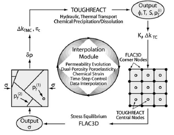 |
Fig. (10). Damage level at two different modeling steps with P-DEM approach [65]. |
The single-modeling numerical approach is another alternative successfully adopted to address the coupled aspects of fractured reservoirs. A single discretization grid is set up to manage mechanics and fluid flow equations via the definition of all the required mechanical and petrophysical parameters. The numerical code adopted to solve this coupled system can be either a fully-coupled or an iteratively-coupled scheme. Several authors have developed single-modeling numerical codes [81-83]. Usually, due to the high complexity and the computational and numerical program demand of the approach, some simplifications were introduced in the description of the physics of the phenomena. For example, Huang and Ghassemi [82] adopted the FEM code to describe overlapping meshes (one for matrix and one for fractures) (Fig. 11) and they also implemented a dynamic permeability change to couple mechanics with fluid-flow, but their model did not consider shear failure of the fracture. Furthermore, the model of Wassing et al. [83], simulated fracture reactivation during geothermal operations by using a single-phase Finite-Difference model (FLAC3D) to solve the coupled problem within single numerical code. Their model includes heterogeneity and shear failure on the fracture planes but the flow is limited to the fracture grid-blocks only.
5.1. Discrete Fracture Network
Discrete fracture network (DFN) modeling represents an alternative to continuum approaches for discontinuity analysis: DFN has been proven to realistically simulate a large number of fractures at reservoir scale by having connectivity of the faults and joints. The fractures are defined explicitly as individual elements within the multi-dimensional space of the model. Their physical properties (such as storage and/or transmissibility) as well as their geometrical properties (such as orientation, size and volume) are assigned statistically to each of the fracture elements individually depending on the measured values and interpreted geological maps. Fig. (12) shows a general example of a three-dimensional DFN model starting from actual fractured reservoir.
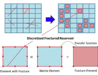 |
Fig. (11). Overlapping mesh used by Huang and Ghassemi [82] for fracture reactivation. |
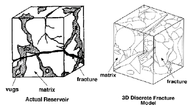 |
Fig. (12). Three-dimensional DFN grid based on actual reservoir [84]. |
The DFN approach has been applied widely and successfully in different investigation domains: geothermal reservoirs [85, 86], interaction between natural and induced fractures [40] and microseismicity [86]. In particular, Kohl and Mégel [86], employed statistical fractures in a discrete fracture network, in order to honor the available data of the Soultz geothermal site. They were able to arrive at a reasonable match of both the injectivity during stimulation of one of the wells and the associated induced seismicity. The model developed by Delorme et al. [75] was able to investigate fluid-flow, permeability alteration and microseismicity interaction during fluid injection in a fractured shale reservoir. Fig. (13) shows natural fracture reactivation during fluid injection modeled by the DFN approach.
The main challenge of this methodology consists of the required number of concurrent simulations. Since the fracture network is randomly generated based on statistical data, one single realization is not sufficient. Multiple cases have to be generated and computed to establish a statistically valid solution.
6. MODELING THE INTERACTION BETWEEN NATURAL FRACTURES AND HYDRAULIC FRACTURING
The coupled fluid-mechanical configuration (rock geometry, stress distribution, and pore pressure) of a formation subjected to hydraulic fracturing is strongly affected by the presence of natural fractures in unconventional reservoirs, which can lead to the development of complex fracture geometries. Therefore, to optimize hydraulic fracturing design it is important to take into account the pre-existing natural fractures during the modeling phase.
The developed and implemented approaches for hydraulic fracturing and pre-existing fracture opening and reactivation available in the technical literature and summarized in the previous paragraphs, were varyingly combined by different authors to address the problems.
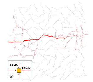 |
Fig. (13). DFN model simulating fracture reactivation [41]. |
The modelling of the induced fracture propagation in a naturally fractured reservoir was addressed via the BEM approach by Koshelev and Ghassemi [87] and via the PKN approach by Potluri [88], while Weng et al. [4] combined a discrete fracture network with a P3D fracture propagation simulation.
[40] demonstrated through their FEM model that discontinuities (fractures/faults/joints) consistently arrest the propagating hydraulic fracture. Their studies demonstrated that geometrical (orientation) and mechanical (strength) parameters of the natural fracture in combination with the in-situ stresses are the most prominent factors affecting the induced hydraulic fracture propagation. Fig. (14) shows schematically a possible interaction between the natural fracture and the propagating hydraulic fracture.
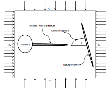 |
Fig. (14). Schematic of NF interacting with HF [41]. |
The XFEM numerical code developed by Dahi-Taleghani and Olson [44] allowed the induced fractures to cross the natural fracture elements and thus propagate independently. They demonstrated that stress anisotropy could enhance the natural fracture interaction effects on hydraulic fracturing.
Fu et al. [41] developed a modular coupled model, using a finite volume method (FVM) to solve the fluid-flow problem, a FEM approach to solve the geomechanics one, a geomechanical joint model to resolve interfaces, and a re-meshing module to reshape the grid during hydraulic fracturing. The modeling approach was validated via a KGD model and laboratory results.
The interaction between natural fractures and propagating hydraulic fractures is a complex phenomenon to model where heterogeneity in the rock system can lead to high uncertainties in the modeling results. The modeling approach adopted must be able to take into account the parameters for both hydraulic fractures and natural fractures, and effective model interaction of both. Use of XFEM allows the model to simulate interaction without the need of re-meshing where hydraulic fractures interact with natural fractures compared to the FEM.
7. MODELING MICROSEISMICITY
Microseismicity related to subsurface operations like injection of water, gas, nuclear waste, carbon dioxide (CO2) sequestration and hydraulic fracturing is becoming a safety issue. On the other hand, it has long been recognized as a very useful tool to acquire information related to the movement of the fluids or gas in the subsurface – microseismic clouds have been used for a long time to determine the effectiveness of the hydraulic fracturing treatment in the hydrocarbon industry and to map the stimulated reservoir volume (SRV). Microseismic and seismic events have also been recorded inside or around the reservoirs, which have critical faults nearby. Van Wees et al. [89] presented an interpretation of seismicity induced by gas production in The Netherlands and concluded that the differential compaction of the depleting reservoir was the major cause of the observed seismicity. Such information is crucial in efforts to predict future seismicity.
Modeling microseismicity implies the prediction of microseismic events using coupled models for faults/fracture reactivation and/or stimulated induced fractures. There are, however, only few reports on such studies that apply to microseismicity during hydraulic fracture treatment in shale gas reservoirs.
The most common approach to predict microseismicity is to qualitatively simulate microseismic events by indirectly interpolating deformation on the fracture plane either to an event location or by use of indirectly estimated magnitude values. The general requirements for quantitative prediction of microseismicity during fracture reactivation are the failing area of fracture, the mechanical properties (and in particular the shear modulus) of the formation and the shear displacements on the fracture plane. Most of the models based on a two-dimensional geomechanics domain fail to quantitatively predict the magnitude of microseismic events, as the area of failure is not known, and they can only predict the location of the event.
Angus et al. [90] developed a model, which can predict pseudo-scalar moments of seismic events for a reservoir in production with two faults. However, they did not consider fracture shear slip during fluid injection (hydraulic fracturing) and consequently could not predict event magnitudes.
Guest and Settari [91] presented a 2D model that can predict qualitatively the seismic events but to quantitatively predict event magnitudes the fracture area is needed which cannot be determined with a 2D model.
Baisch et al. [92] developed a FEM code to model microseismicity resulting from enhanced geothermal operations near a fault zone. Wassing et al. [83] developed their model using FLAC3D, a finite difference model for predicting induced microseismicity from water injection in EGS reservoirs. They used fault/fracture rupture area from the three-dimensional models to determine resulting microseismicity when fault/fracture is shearing during water injection. These models can be ported for possible applications of fracture reactivation in unconventional hydrocarbon reservoirs.
Chorney et al. [93] used a bounded particle model (discrete element model) for rock tri-axial tests and resulting microseismic events. At laboratory scale, their model could predict deformation for intact and fractured samples, but it was not capable of simulating resulting microseismicity.
William-Stroud et al. [94] reported a modeling study that addresses reactivation of natural fractures by defining them as a discrete fracture network (DFN). Their model localized microseismic events by determining the shear failure location. Fig. (15) compares the microseismic events from the DFN reactivation with the microseismic event cloud in the reservoir.
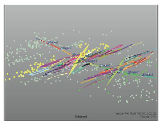 |
Fig. (15). Comparison of Microseismic events with DFN reactivation [94]. |
DISCUSSION
Hydraulic fracturing in unconventional reservoirs is a multi-physics problem and coupled models are thus needed to study it. The fully coupled scheme is the most comprehensive method to solve a thermo-hydro-mechanical problem, because it captures the actual coupling of multiple physics. At the same time, however, it is the one with the most complex system of equations to achieve problem solution and it implies a higher computational cost. The iteratively coupled methods provide easier numerical handling of the problem with less computational cost, but they need a more delicate handling of the time-stepping involved. The one-way coupled approach reduces computational costs even further, but it is only suitable for problems where the mechanical behavior of the rock is not very sensitive to the fluid flow, or vice-versa.
Hydraulic fracture modeling started from analytical formulations like the PKN and KDG models. These were improved in the P3D and PL3D models, which are currently widely used within the industry as they are user-friendly and have been thoroughly applied.
The different discretization techniques for modeling hydraulic fractures have their own advantages and disadvantages – relating to the problem being modeled. The FEM is limited by grid-refinement requirements, which results in high computational times. The XFEM is an extension of the FEM to handle discontinuities as introduced by fractures, and thus circumvents the grid refinement required for regular FEM. However, it has not yet been thoroughly tested for complex fracture networks. The BEM eliminates the need of a discretization around the fracture, but has limitations to the number of cells in the system. The DEM is a promising approach for modeling heterogeneous systems and can model hydraulic fracturing effectively for lab-scale samples, but the upscaling to field operations and the calibration of the model parameters represents its main challenge.
The presence of faults can be viewed as weakness planes in an intact rock. They affect drastically the way hydraulic fractures propagate. Depending on the circumstances, natural fractures can arrest the propagation of a hydraulic fracture or allow the hydraulic fracture to cross it. Modeling this interaction is complex and needs advanced coupled models, which can handle fault reactivation in combination with its interaction with hydraulic fractures. Different modeling approaches in combination with different discretization schemes to simulate the presence of natural fractures during hydraulic fracturing have been proposed. A fully coupled flow-mechanical modeling approach is required to adequately describe the dynamically changing properties when faults are reactivated and the fluid flow behavior is changed.
The ability of monitoring and modeling microseismicity during hydraulic fracturing is important from the safety point of view, but also for better understanding and mapping stimulated reservoir volume (SRV). Inclusion of microseismic modules in geomechanical models, which can quantitatively predict seismicity connected with hydraulic fracturing and fracture reactivation, is essential. Such models need to be capable of predicting locations and magnitudes of seismic events in a statistical manner, in order to connect the observed seismic clouds and the frequency-magnitude relationships. Only 3D geomechanical models can provide a measure of induced microseismicity that can be compared with field-recorded events. Only a few such models are currently available.
CONCLUSION
This paper provides an overview of the modeling approaches used for hydraulic fracturing and related phenomena, like fracture reactivation and microseismicity, in unconventional hydrocarbon reservoirs. The review is intended to support the selection of effective modeling approaches for various applications. To this end, different coupling strategies are presented and discussed in view of their merits and shortcomings. Furthermore, the major issues related to using the different possible discretization schemes when modeling hydraulic fractures are discussed. A particularly important issue is the need of including naturally present fractures when modeling hydraulic fracturing in a naturally fractured reservoir system. Therefore, a brief review of the research carried out to study the interaction between natural and induced fractures is also provided. Finally, a concise survey on modeling setups developed to predict microseismicity in reservoirs undergoing fracturing or fracture reactivation is presented.
CONFLICT OF INTEREST
The authors confirm that this article content has no conflict of interest.
ACKNOWLEDGEMENTS
Declared none.
REFERENCES
| [1] | Chong KK, Grieser WW. A completion guide book to shale-play development: A review of successful approaches towards shale-play stimulation in the last two decades. In: Paper CSUG/SPE 133874 Presented at the Canadian Unconventional Resources & International Petroleum Conference; October 19-21; Calgary, Alberta, Canada.. 2010. |
| [2] | Philipp SL, Afsar F, Gudmundsson A. Effects of mechanical layering on hydrofracture emplacement and fluid transport in reservoirs. Front Earth Sci 2013; 1(4) |
| [3] | Daneshy AA. Hydraulic fracture propagation in the presence of plane of weakness. In: Paper SPE-4852-MS presented at SPE European Spring Meeting; May 29-30; p. 7, Amsterdam, Netherlands. 1974. |
| [4] | Weng X, Kresse O, Cohen CE, Wu R, Gu H. Modeling of hydraulicfracturenetwork propagation in a naturally fractured formation. SPE Prod Oper 2011; 26(4): 368-80. |
| [5] | Warpinski NR, Teufel LW. Influence of geologic discontinuities on hydraulic fracture propagation (includes associated papers 17011 and 17074). J Petr Tech 1987; 39(02): 209-20. |
| [6] | Blanton TL. An experimental study of interaction between hydraulically induced and pre-existing fractures In: SPE Unconventional Gas Recovery Symposium. Pittsburgh, Pennsylvania, USA 1982. |
| [7] | Blanton TL. Propagation of hydraulically and dynamically induced fractures in naturally fractured reservoirs In: SPE Unconventional Gas Technology Symposium. Louisville, Kentucky, USA 1986. |
| [8] | Azeemuddin M, Ghori SG, Saner S, Khan MN. Injection-induced hydraulic fracturing in a naturally fractured carbonate reservoir: A case study from Saudi Arabia In: International Symposium and Exhibition on Formation Damage Control. Lafayette, Louisiana, USA 2002. |
| [9] | Zhou J, Chen M, Jin Y, Zhang G-q. Analysis of fracture propagation behavior and fracture geometry using a tri-axial fracturing system in naturally fractured reservoirs. Int J Rock Mech Min 2008; 45(7): 1143-52. |
| [10] | Fjær E, Horsrud P, Raaen AM, Risnes R, Holt RM. Petroleum Related Rock Mechanics. 2nd ed. USA: Elsevier 2008. |
| [11] | Zoback MD. Reservoir Geomechanics. Cambridge University Press 2007. |
| [12] | Gudmundsson A. Rock Fractures in Geological Processes. Cambridge University Press 2011. |
| [13] | Rocca V. Development of a fully coupled approach for evaluation of wellbore stability in hydrocarbon reservoirs. Am J Environ Sci 2009; 5(6): 781-90. |
| [14] | Settari A, Sen V. The role of geomechanics in integrated reservoir modeling. The Lead. Edge 2007; 26(2): 622-7. [TLE]. |
| [15] | Gutierrez M, Lewis RW. The Role of Geomechanics in Reservoir Simulation In: Paper 47392-MS Presented at SPE/ISRM Rock Mechanics in Petroleum Engineering. Trondheim, Norway 8-10 July, 1998. |
| [16] | Hettema MHH, Schutjens PMTM, Verboom BJM, Gussinklo HJ. Production-induced compaction of a sandstone reservoir: The strong influence of stress path SPE Reserv Eval Eng 2000; 3(4): 342-7. |
| [17] | Settari AT, Bachman RC, Walters DA. How to approximate effects of geomechanics in conventional reservoir simulation In: SPE Annual Technical Conference and Exhibition. Dallas, Texas, USA 2005. |
| [18] | Tran D, Settari A, Nghiem L. New Iterative coupling between a reservoir simulator and geomechnics module In: SPE/ISRM Rock Mechanics Conference. Irving, Texas, USA 2002. |
| [19] | Rodrigues LG, Cunha LB, Chalaturnyk RJ. Incorporating geomechanics into petroleum reservoir numerical simulation In: Paper SPE-107952-MS Presented at Rocky Mountain Oil & Gas Technology Symposium. Denver, Colorado, USA 16-18 April 2007. |
| [20] | Rutqvist J. Status of the TOUGH-FLAC simulator and recent applications related to coupled fluid flow and crustal deformations. Comput Geosci 2011; 37(6): 739-50. |
| [21] | Dean RH, Gai X, Stone CM, Minkoff SE. A comparison of techniques for coupling porous flow and geomechanics. SPE J 2006; 11(01): 132-40. |
| [22] | Jalali MR, Dusseault MB. Coupled fluid-flow and geomechanics in naturally fractured reservoirs Int J Min Geo-Eng (IJMGE) 2012; 46(2): 105-31. |
| [23] | Howard CC, Fast CR. Optimum fluid characteristics for fracture extension. In: API Drilling and Production Practice. 1951; pp. 261-70. |
| [24] | Gidley JL, Holditch SA, Nierode DE, Veatch RW Jr.. Recent Advances in Hydraulic Fracturing In: SPE Monograph Series. ISBN:978-1-55563-020-1. |
| [25] | Warpinski NR, Moschovidis ZA, Parker CD, Abou-Sayed IS. Comparison study of hydraulic fracturing models - test case: GRI staged field experiment No. 3. SPE Prod Facil 1994; 9(1): 7-16. |
| [26] | Valkó P, Economides MJ. Hydraulic Fracture Mechanics. West Sussex, England: John Wiley & Sons. LTD 1995. |
| [27] | Economides MJ, Nolte KG. Reservoir Stimulation, 3rd ed 2000; ISBN-13: 978-0471491927. |
| [28] | Md. M.Hossain andM. K. Rahman, “Numerical simulation of complex fracture growth during tight reservoir stimulation by hydraulic fracturing. J Petrol Sci Eng 2008; 60(2): 86-104. |
| [29] | Sneddon IN. The distribution of stress in the neighbourhood of a crack in an elastic solid. Proc R Soc Lond A Math Phys Sci 1946; 187(1009): 229-60. |
| [30] | Sneddon IN, Elliot HA. The opening of a Griffith cracks under internal pressure. Q Appl Math 1946; 4: 262-7. |
| [31] | Perkins TK, Kern LR. Widths of hydraulic fractures. SPE J Pet Tech 1961; 13(9): 937-49. |
| [32] | Nordgren RP. Propagation of a vertical hydraulic fracture. SPE J 1972; 12(8): 306-14. |
| [33] | Khristianovic SA, Zheltov YP. Formation of vertical fractures by means of highly viscous liquid In: Proceedings of the 4th World Petroleum Congress. 1955; pp. 579-86. |
| [34] | Geertsma J, de Klerk F. A rapid method of predicting width and extent of hydraulically induced fractures. J Pet Technol 1969; 21(12): 1571-81. |
| [35] | Adachi J, Siebrits E, Peirce A, Desroches J. Computer simulation of hydraulic fractures. Int J Rock Mech Min Sci 2007; 44(5): 739-57. |
| [36] | Rahman MM, Rahman MK. A review of hydraulic fracture models and development of an improved Pseudo-3D model for stimulating tight oil/gas sand. Energ Sources Part A 2010; 32(15): 1416-36. |
| [37] | Clifton RJ, Wang J-J. Adaptive optimal mesh generator for hydraulic fracturing modeling In: The 32nd US Symposium on Rock Mechanics (USRMS). 1991; pp. 607-16. |
| [38] | Biot MA. General theory of three-dimensional consolidation. J Appl Phys 1941; 12(155): 155-64. |
| [39] | Biot MA. Theory of elasticity and consolidation for a porous anisotropic solid. J Appl Phys 1955; 26(182): 182-5. |
| [40] | Rahman MM, Rahman SS. A fully coupled numerical poroelastic model to investigate interaction between induce hydraulic fracture and pre-existing natural fracture in a naturally fractured reservoirs: Potential application in tight gas and geothermal reservoirs In: SPE Annual Technical Conference and Exhibition. New Orleans, Louisiana, USA 2009. |
| [41] | Fu P, Johnson SM, Carrigan CR. An explicitly coupled hydro-geomechanical model for simulating hydraulic fracturing in arbitrary discrete fracture networks. Int J Numer Anal Methods Geomech 2013; 37(14): 2278-300. |
| [42] | Moës N. J. Dolbow, and T. Belytschko, “A finite element method for crack growth without remeshing. Int J Numer Anal Methods Geomech 1999; 46(1): 131-50. |
| [43] | Numerical modeling of multistranded-hydraulic-fracture propagation: accounting for the interaction between induced and natural fractures. SPE J 2011; 16(3): 575-81. |
| [44] | Dahi-Taleghani A, Olson JE. Analysis of multistranded hydraulic fracture propagation: an improved model for the interaction between induced and natural fractures In: SPE Annual Technical Conference and Exhibition. New Orleans, Louisiana, USA 2009. |
| [45] | Keshavarzi R, Mohammadi S. A new approach for numerical modeling of hydraulic fracture propagation in naturally fractured reservoirs In: SPE/EAGE European Unconventional Resources Conference and Exhibition. Vienna, Austria 2012. |
| [46] | McClure MW, Horne RN. Discrete Fracture Network Modeling of Hydraulic Stimulation, Coupling Flow and Geomechanics. Springer International Publishing 2013. |
| [47] | Bobet A. “Numerical methods in geomechanics. Arab J Sci Eng 2010; 35(1B): 27-48. [Accessed Sept. 2015]. |
| [48] | Crouch SL. Solution of plane elasticity problems by displacement discontinuity method. Int J Numer Methods Eng 1976; 10(2): 301-43. |
| [49] | The role of friction and secondary flaws on deflection and re-initiation of hydraulic fractures at orthogonal pre-existing fractures. Geophys J Int 2006; 166(3): 1454-65. |
| [50] | Safari MR, Ghassemi A. 3D analysis of huff and puff and injection tests in geothermal reservoir. In: 36th Workshop on Geothermal Reservoir Engineering. 2011. [[Accessed Sept. 2015]]; Available from: https://pangea.stanford.edu/ERE/pdf/IGAstandard/SGW/2011/safari.pdf. |
| [51] | Tarasovs S, Ghassemi A. On the role of thermal stress in reservoir stimulation In: 37th Workshop on Geothermal Reservoir Engineering. Available from: https://pangea.stanford.edu/ERE/pdf/IGAstandard/SGW/2012/Tarasovs.pdf, 2012. [Accessed Sept. 2015] |
| [52] | Lee SH, Ghassemi A. Three-dimensional thermo-poro-mechanical modeling of reservoir stimulation and induced seismicity in geothermal reservoir In: 36th Workshop on Geothermal Reservoir Engineering, 2011. Available from: https://pangea.stanford.edu/ ERE/pdf/IGAstandard/SGW/2012/Tarasovs.pdf, 2012. [Accessed Sept. 2015] |
| [53] | Yamamoto T, Kitano K, Fujimitsu Y, Ohnishi H. Application of simulation code, GEOTH3D, on the Ogachi HDR site In: 22nd Annual Workshop on Geothermal Reservoir Engineering. 1997; pp. 203-12. [ [Accessed Sept. 2015]]; Available from: http://www.geothermal- energy.org/pdf/IGAstandard/SGW/1997/Yamamoto.pdf |
| [54] | Vassilellis G, Bust V, Li C, Cade R, Moos D. Shale engineering application: the MAL-145 project in West Virginia In: Canadian Unconventional Resources Conference. Calgary, Alberta, Canada 2011. |
| [55] | Kelkar S, Lewis K, Hickman S, Davatzes NC, Moos D, Zyvoloski G. Modeling coupled thermal- hydrological-mechanical processes during shear stimulation of an EGS well In: 37th Workshop on Geothermal Reservoir Engineering. Available from: https://pangea.stanford.edu/ERE/db/GeoConf/papers/SGW/2012/Kelkar.pdf, 2012. [Accessed Sept. 2015] |
| [56] | Cundall PA, Strack OD. A discrete numerical model for granular assemblies. Geotechnique 1979; 29(1): 47-65. |
| [57] | Cleary PW. Extensions of the hybrid method for granular flows In: Proceedings 5th International Computational Techniques and Applications Conference. Adelaide, Australia 1991; pp. 141-8. |
| [58] | Cundall PA. UDEC- A generalized distinct element program for modeling jointed rock” Final Tech Rep Eur Res Office (US Army Contract) NTIS order no AD-A087 610/2 1980 [ [Accessed Sept. 2015]]; Available from: http://www.dtic.mil/cgi-bin/ GetTRDoc?Location=U2&doc=GetTRDoc.pdf&AD=ADA087610 |
| [59] | Cundall PA, Hart RD. Development of generalized 2-D and 3-D distinct element programs for modeling jointed rock” Final Technical Report European Research Office (US Army Contract) Misc Paper SL-85-1 Structures Laboratory []; Available from: http://www.dtic.mil/dtic/tr/fulltext/u2/a153927.pdf, 1985. [Accessed Sept. 2015] |
| [60] | Walton OR. "Particle dynamics modeling of geological materials", In: Rep. UCRL-52915, Lawrence Livermore National Laboratory, 1980. |
| [61] | Starfield AM, Cundall PA. Towards a methodology for rock mechanics modelling. Int J Rock Mechn Min Sci Geomech 1988; 25(3): 99-106. |
| [62] | Hart R. P.A. Cundall and J. Lemos, “Formulation of a three-dimensional distinct element model- Part II. mechanical calculations for motion and interaction of a system composed of many polyhedral blocks. Int J Rock Mechn Min Sci Geomech 1988; 25(3): 117-25. |
| [63] | Nagel N, Gil I, Sanchez-Nagel M, Damjanac B. Simulating hydraulic fracturing in real fractured rocks - overcoming the limits of pseudo3d models In: SPE Hydraulic Fracturing Technology Conference. The Woodlands, Texas, USA 2011. |
| [64] | PFC2D (Particle Flow Code in 2 Dimensions) Version 3.1, Manual. Itasca Consulting Group, Inc. User’s Manual, 2006. |
| [65] | Min SK, Zhang Z, Ghassemi A. Hydraulic fracturing propagation in heterogeneous rock using the VMIB method In: 35th Workshop on Geothermal Reservoir Engineering. Available from: http://www.geothermal-energy.org/pdf/IGAstandard/SGW/2010/min.pd, 2010. [Accessed Sept. 2015] |
| [66] | Deng S, Podgorney R, Huang H. Discrete element modeling of rock deformation, fracture network development and permeability evolution under hydraulic stimulation In: 36th Workshop on Geothermal Reservoir Engineering. Available from: http://www.geothermal-energy.org/pdf/IGAstandard/SGW/2011/deng.pdf, 2011. |
| [67] | Valliappan S, Khalili-Naghadeh N. Flow through fissured porous media with deformable matrix. Int J Numer Method Eng Sci 1990; 29(5): 1079-94. |
| [68] | Flow through fissured porous media with deformable matrix: Implicit formulation. Water Resour Res 1991; 27(7): 1703-9. |
| [69] | Chen H-Y, Teufel LW. Coupling fluid-flow and geomechanics in dual-porosity modeling of naturally fractured reservoirs In: SPE Annual Technical Conference and Exhibition. San Antonio, Texas, USA 1997. |
| [70] | Gutierrez M, Lewis RW, Masters I. Petroleum reservoir simulation coupling fluid flow and geomechanics. In: SPE Reservoir Eval Eng. 2001; 4.(03) |
| [71] | Nassir M, Settari A, Wan RG. Prediction and optimization of fracturing in tight gas and shale using a coupled geomechanical model of combined tensile and shear fracturing In: SPE Hydraulic Fracturing Technology Conference. The Woodlands, Texas, USA 2012. |
| [72] | Ghafouri HR, Lewis RW. A finite element double porosity model for heterogeneous deformable porous media. Int J Numer Anal Methods Geomech 1996; 20(11): 831-44. |
| [73] | Samier P, Onaisi A, Fontaine G. Comparisons of uncoupled and various coupling techniques for practical field examples. SPE J 2006; 11(01): 89-102. |
| [74] | Samier P, De Gennaro S. Practical iterative coupling of geomechanics with reservoir simulation”. Paper SPE-106188-MS. In: SPE Reservoir Simulation Symposium. Houston, Texas, USA 2007. |
| [75] | Delorme M, Daniel J-M, Kada-Kloucha C, Khvoenkova N, Schueller S, Souque C. And efficient model to simulate reservoir stimulation and induced microseismic events on 3D discrete fracture network for unconventional reservoirs In: Unconventional Resources Technology Conference. Denver, Colorado, USA 2013. |
| [76] | Olden PW, Jin M, Smart BG, Tehrani AD. Rock mechanics factors in enhanced fluid simulation Int J Rock Mech Min SciGeomech 1995; 32(5): 529-35. |
| [77] | Bagheri M, Settari A. Modeling of geomechanics in naturally fractured reservoirs. SPE Reservoir Eval Eng 2008; 11(01): 108-18. |
| [78] | Cappa F, Rutqvist J. Modeling of coupled deformation and permeability evolution during fault reactivation induced by deep underground injection of CO2. Int J Greenh Gas Control 2011; 5(2): 336-46. |
| [79] | Rutqvist J, Rinaldi AP, Cappa F, Moridis GJ. Modeling of fault reactivation and induced seismicity during hydraulic fracturing of shale-gas reservoirs. J Petrol Sci Eng 2013; 107: 31-44. |
| [80] | Gan Q, Elsworth D. Analysis of fluid injection-induced fault reactivation and seismic slip in geothermal reservoirs. J Geophys Res Solid Earth 2014; 119(4): 3340-53. |
| [81] | Ji L, Settari A, Sullivan RB, Orr D. Methods for modeling dynamic fractures in coupled reservoir and geomechanics simulations In: SPE Annual Technical Conference and Exhibition. Houston, Texas, USA 2004. |
| [82] | Huang J, Ghassemi A. Geomechanical evolution of fracture reservoirs during gas production In: Paper ARMA 12-321, Presented at 46th US Rock Mechanics/Geomechanics Symposium. Chicago, Illinois, USA 2012.24-27 June |
| [83] | Wassing BB, van Weesand J D, Fokke P A. Coupled continuum modeling of fracture reactivation and induced seismicity during enhanced geothermal operations. Geothermics 2014; 52: 153-64. |
| [84] | La Pointe PR, Eiben T, Dershowitz WS, Wadleigh EE. Compartmentalization analysis using discrete fracture network models In: Fourth International Reservoir Characterization Conference. 1997; pp. 115-34. |
| [85] | Sausse J, Dezayes C, Genter A, Bisset A. Characterization of fracture connectivity and fluid flow pathways derived from geological interpretation and 3D modelling of the deep seated EGS reservoir of Soultz (France) In: 33rd Workshop on Geothermal Reservoir Engineering. Available from: http://www.geothermal-energy.org/pdf/IGAstandard/SGW/2008/sausse.pdf, 2008. [Accessed Sept. 2015] |
| [86] | Kohl T, Mégel T. Predictive modeling of reservoir response to hydraulic stimulations at the European EGS site Soultz-sous-Forets. Int J Rock Mech Min Sci 2007; 44(8): 1118-31. |
| [87] | Hydraulic fracture propagation near a natural discontinuity” In: Twenty-Eight Workshop on Geothermal Reservoir Engineering https://earthsciences.stanford.edu/ERE/pdf/IGAstandard/SGW/2003/Koshelev.pdf 2003 [[Accessed Sept. 2015]]; |
| [88] | Potluri NK. Effect of a natural fracture on hydraulic fracture propagation In: SPE European Formation Damage Conference. Sheveningen, The Netherlands 2005. |
| [89] | Van Wees JD, Buijze L, Van Thienen-Visser K, et al. Geomechanics response and induced seismicity during gas field depletion in the Netherlands. Geothermics 2014; 52: 206-19. |
| [90] | Angus DA, Kendall J-M, Fisher QJ, et al. Modellingmicroseismicity of producing reservoir from coupled fluid-flow and Geomechanical simulation. Geophys Prospect 2010; 58(5): 901-14. |
| [91] | Guest A, Settari T. Numerical model of microseismicity in hydrofracturing: our prediction for seismic moment tensors In: Presented at GeoConvention 2010, Calgary, Alberta, Canada, May 10-14 2010. Available from: http://www.searchanddiscovery.com/abstracts/ pdf/2014/90172cspg/abstracts/ndx_guest.pdf [Accessed Sept. 2015]. |
| [92] | Baisch S, Voros R, Weidler R, Wyborn D. Investigation of fault mechanisms during geothermal reservoir stimulation experiments in the cooper basin, Australia. Bull Seismol Soc Am 2009; 99(1): 148-58. |
| [93] | Chorney D, Jain P, Grob M, Van Der Baan M. Geomechanical modeling of rock fracturing and associated microseismicity. Leading Edge (Tulsa Okla) 2012; 31(11): 1348-54. |
| [94] | William-Stroud SC, Barker WB, Smith KL. Induced hydraulic fractures or reactivated fractures? Modeling the response of natural fracture networks to stimulation treatments Paper ARMA 12-667 2012 [[Accessed Sept. 2015]]; In: Presented at 46th U.S. Rock Mechanics/Geomechanics Symposium; 24-27 June; Chicago, Illinois, USA.. 2012. Available from: https://www.onepetro.org/download/ conference-paper/ARMA-2012-667?id=conference-paper%2FARMA-2012-667. |


